Toggle lever: huge force near the dead point
You squeeze a toggle clamp with two fingers and it holds a part with a force you couldn't match with your whole hand. There are no gears or screws inside: just two pinned links that, as they straighten toward alignment, multiply whatever you apply at the handle into enormous force. And when they reach the end, they hold: the part stays clamped and you let go, because the mechanism has locked itself. All of that magic — the force that appears out of nowhere and the latch that won't reopen — happens in the few degrees that separate the two links when they're about to go straight. Understanding exactly what happens at that angle is understanding the entire mechanism.
Why force spikes near the dead point
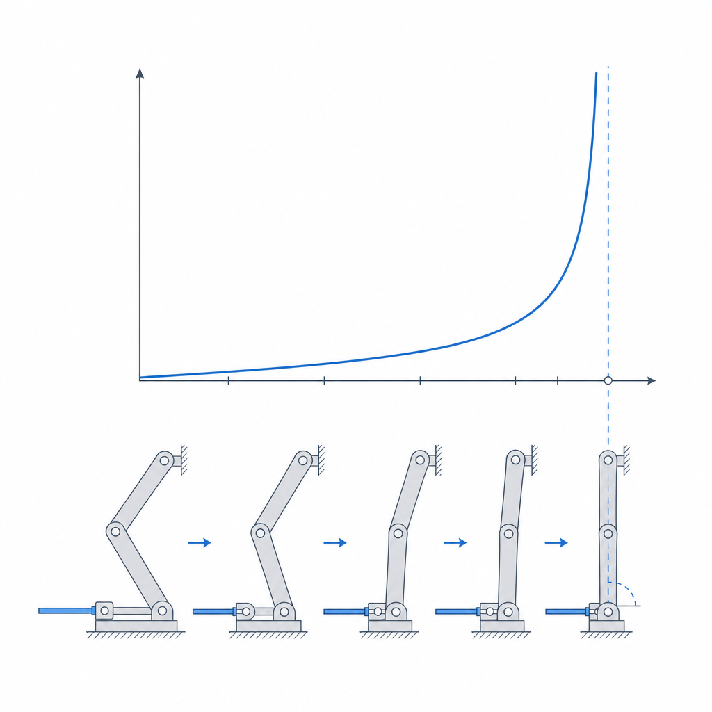
A toggle reduces to two links joined by a central pin, with the other two ends anchored: one to a fixed point, the other to the part being clamped. You push the central pin toward the line connecting the two anchors, and as the links approach straight — the dead point, where all three pins are aligned — the output force spikes.
The reason is purely geometric, and the angle is the way to see it. Call θ the angle each link makes with the line through the anchors. The force you apply at the central pin is nearly perpendicular to that line, but the useful force — the clamping force — comes out along the links, nearly parallel to it. For a symmetric toggle pushed at the central pin, the output force equals F_in divided by 2·tan θ: the factor of two appears because your push is split between the two links, and 1/tan θ does the rest. With the links at 45°, you get half a unit of output per unit of input; what's interesting isn't the absolute number but how it grows as the angle closes. At 10° the cotangent is almost six; at 2°, almost thirty; and as θ approaches zero, tan θ approaches zero and the output force approaches infinity, in theory. It's not that the mechanism creates energy. It's that, near alignment, a large hand movement produces only a tiny closing at the anchors: almost all of your input projects as clamping force and less and less is spent on moving the pin. You trade travel for force: it's what any mechanical amplifier does.
You have to separate two things that often get confused. One is the geometric advantage of the toggle, the part captured by 1/(2·tan θ). The other is the total advantage of the mechanism, which also includes the hand-lever arm you use to drive the pin. The total advantage is the product of the two: the lever scales the whole curve linearly, and the toggle's geometry spikes it at the end. That's why, near closing, shaving a few degrees off θ is worth more than doubling the lever arm: in that regime the cotangent rules. Far from the dead point, things reverse: there the lever arm is your best multiplier.
That theoretical infinity is, of course, an abstraction: friction, link bending, and pivot play impose a very real ceiling well before you reach it. But the practical lesson is solid: you don't set the clamping force with the hand lever, but with how close to the dead point you let the mechanism work.
The latch that holds itself: crossing the dead point
If the toggle only amplified force, you'd have to keep pushing to hold the clamp, and as soon as you let go, the load would reopen the mechanism. What turns it into a latch is taking the links a little past the dead point, not stopping right at it. That's the over-center.
Think it through in terms of the return load: the clamped part pushes back, trying to reopen the mechanism. Before the dead point, that force has a component pushing the links open, so the mechanism would release on its own. Right at alignment, the return force points exactly along the links and has no component to open or close: it's a singular point, a knife-edge where the mechanism's stiffness spikes and the reaction changes sign. But if you go past alignment by a few degrees, the geometry inverts: now the same return load pushes the links the other way — against a stop — instead of open. The mechanism self-locks. The harder the load pulls to close, the harder it presses against the stop. You take your hand off and it stays clamped, because the load itself is now what shuts the latch.
For that latch to bite, you need more than geometry: you need the loop to deform a little as it crosses. Links, pivots, stop, and frame form an elastic loop, and as it passes the dead point that loop compresses slightly and stores a preload; that preload is what keeps the clamping force alive. In FDM, with a low modulus — on the order of 2 to 3 GPa in PLA, less in PETG — and play everywhere, the loop is soft. If the part you're clamping is also rigid and gives nothing, the over-center may barely "click": there's no deformation to store, no preload, and the latch ends up loose. You need something in the loop to give just enough — the part itself, a link, a stop with a flex point — so the over-center has a source of preload.
That's why a toggle clamp gives that characteristic click at the end of the stroke: you're crossing the dead point and loading the loop. That physical stop isn't an add-on; it's half the mechanism. Without it, the over-center has nothing to lock against and the links would keep going until they folded over to the other side.
What it's for: large clamping force from little effort, and it stays put
Use a toggle whenever you need large clamping force from little input, and you want it locked without holding it. It's the kinematics of workbench hold-down clamps, small presses, the lever latches on cases and luggage, manual punches, and any jaw that has to close firmly and stay closed. The mechanism's signature is a combination almost nothing else offers: enormous force gain at the end of the stroke plus self-locking for free.
A toggle is not a travel mechanism. Near the dead point, where it gives all its force, the output barely moves: it amplifies force at the cost of stroke, exactly the opposite of what you want if what you need is displacement. If what you need is to move far and fast, this isn't your mechanism; if you need to clamp hard and have it stay put, nothing is this simple.
Designing it for FDM: size for the peak force
The trap of printing a toggle is this: the force that justifies the mechanism is also the force that breaks it. Near the dead point, the links and pins see the amplified force, not the one you apply. Sizing for the average hand force guarantees failure; you have to size for the peak near closing, which can be an order of magnitude larger.
Near alignment, the links work essentially in compression along their axis, and that conditions how you print them. Lay them out so the beads run along their length, parallel to the force: that way the load travels through the continuous material of the beads. The danger of a thin link under axial compression isn't that it delaminates — the between-layer plane is weak in tension and shear, not in compression — but that it buckles: it bows suddenly once it exceeds its critical load. And once it bows, bending sets in, and bending does open the layers on the face that goes into tension. The same thing happens if the pivots don't line up well: the eccentricity introduces a moment that bends the link. That's why you want generous cross-sections and short, sturdy links; a thin, slender link is the first to buckle, exactly when the force is highest. Layer orientation matters as much as cross-section, and for the same reasons explained in Layer orientation for motion.
The pins are the other critical point. Under the amplified load, a short pin between two lugs works mostly in bending — like a beam supported at its ends and loaded at the center — plus shear, and on top of that crushes the printed pivot eye. A plastic pin against a plastic eye, under toggle force, is almost always insufficient: the pin bends, the eye goes oval, the play grows, and with it the dead point shifts. Consider metal shafts and bushings — a steel pin, a metal sleeve embedded in the eye — so the load is carried without the plastic bending or flowing; it's exactly the scenario of Embedded hardware: magnets, bearings, and inserts. And model the over-center's physical stop with material to spare, because the entire return load bears on it: that stop defines the closed position and limits overtravel, so size it like a load-bearing surface, not like a detail.
| Element | Criterion | Why |
|---|---|---|
| Links | Layers along the axis, generous cross-section, short link | they work in compression near the dead point; thin ones buckle, then bend and delaminate |
| Pins | Metal shaft + bushing, not plastic-on-plastic | they bend and shear under the peak load; in plastic they ovalize the eye |
| Pivot eyes | Thick wall, almost all perimeter | resist crushing under the closing force |
| Over-center stop | Load-bearing surface with material to spare | makes the self-lock real and limits overtravel |
| Overtravel | 1 to 3° past the dead point | margin so creep doesn't return the mechanism |
| Pivot clearance | Minimum that still allows free rotation | play shifts the dead point and ruins the lock |
The failure modes all cluster near closing
There are three sudden ways a printed toggle fails, plus a slow one, and all of them show up where the force is greatest.
The first is breakage of links or pins from the amplified load. If a link snaps, look at the fracture plane: a crack that follows the layer plane — link laid flat, a horizontal crack — gives away bending, almost always from buckling or from misaligned pivots that opened the layers in tension. A break that cuts across the beads is the bead giving way in compression or the link being too thin. If a pin gives way, it wasn't sized for the peak, only for the hand force. All of it is fixed at the source: correct orientation, sufficient cross-section, short links, and metal in the pins.
The second is loss of self-locking, and it's the most insidious because the mechanism seems to work until it suddenly doesn't. The over-center depends on the dead point being where you designed it, and the dead point depends on the distances between pins. If the pivot play grows — because the eye went oval, because you left too much slack, because the plastic flowed under sustained load — the dead point shifts and the mechanism may stop short of crossing it: it clamps less and, worse, stops locking. That's why a toggle wants the minimum clearance that still lets it turn freely, not the generous clearance of an ordinary pivot. This is the fine balance covered in Tolerances for moving parts, applied to a case where a tenth of a millimeter too much doesn't just produce play: it shifts the closed position and releases the mechanism.
The third is crushing of the pivot eyes. Under the closing force, the plastic eye ovalizes against the pin, reopening play and feeding the loss of lock in a vicious loop. The defense is the same as for any heavily loaded hole: thick wall, almost all perimeter, and a metal bushing that spreads the contact pressure over material that doesn't flow.
There's a fourth enemy that isn't a sudden failure but a slow one: creep. At rest, a closed toggle draws no power, but plastic under sustained load flows, and over time it relaxes the loop's preload. The latch can still be geometrically past the dead point and still loosen: the clamping force decays even though the mechanism hasn't opened. It's the underlying reason not to skimp on overtravel or cross-section, and to prefer materials less prone to creep when the toggle has to stay loaded for days.
If all of this sounds like "design for the force you don't see," that's exactly what it is: the toggle pays for its enormous force with an equally high structural demand, in the same few degrees where it delivers the payoff. Size for that peak load, orient the layers so the continuous material carries it, fix the pivots with metal, make the stop real: you'll have a latch that clamps with two fingers and won't let go. And before you sign off on the pivot fit, run through Tolerances for moving parts, because in a toggle, clearance isn't about comfort: it's what decides whether the mechanism locks or opens.