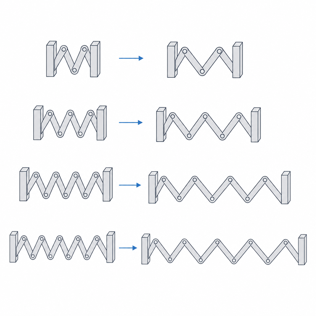
Serpentine flexure: stiffness tuned by segment count
A straight cantilever is the simplest flat spring you can print, but it has a ceiling: to get a lot of travel at low force you'd have to make it impossibly long, and you rarely have that much room. The serpentine flexure solves exactly that. You take that same cantilever, fold it into a zigzag, and chain one run after another so the effective length folds back on itself: you fit a long arm into a fraction of the space it would take stretched out. The consequence isn't cosmetic; it's mechanical. Each run contributes its own compliance, and those compliances add up. The result is a monolithic, flat spring with no parts to assemble, whose force you tune by segment count rather than by changing the material.
Compliance in series: why chaining runs softens the spring
The key to the serpentine is that its runs work in series, not in parallel. When you push the free end, the load travels down the first run, turns at the bend, travels down the second, turns again, and so on to the anchor. Each run flexes under that same load, and each flex adds its share of displacement to the total. It's the mechanical picture of springs chained one behind another: the travel of the whole is the sum of the individual travels, while the force passing through them is the same through all of them.
Adding compliances in series is exactly the opposite of adding stiffnesses. Compliance—how much it moves per unit of force—grows with every run you add; stiffness—how much force you need per unit of motion—falls. But that softening comes with a condition worth keeping in mind from the start: it only holds cleanly if adding runs doesn't shorten the ones you already have, that is, if you make the overall spring longer. The compliance of each run goes with the cube of its length, so a run half as long is eight times stiffer. If you cram more segments into the same gap, each one gets shorter, stiffens cubically, and that stiffening can erode—or even reverse—the softening you expected from chaining more runs.
When you do have room to lengthen, the segment count becomes a clean, discrete, predictable lever for bringing the force to the value you want without touching the width, the thickness, or the plastic.
Long travel without overworking the material: where the strain goes
The other half of the explanation isn't in the force, it's in the travel. A simple cantilever forced to deliver all the displacement the serpentine delivers would concentrate enormous strain at its root: bending a beam loads the outer fiber at the fixed end, and that's where the material reaches its limit first. The more travel you ask of a single arm, the closer to fracture that root works.
The serpentine spreads that work, but it's worth understanding to what extent. The total displacement is distributed among many runs, so each one only has to flex a little, and the peak strain at each local root drops relative to an equivalent straight cantilever. That effect is genuine, and it's the basis of the design. What isn't true is that the stress ends up equalized between runs: in a cantilever, the bending moment isn't uniform—it grows toward the fixed end. The runs near the anchor see more moment—and more stress—than those at the free end, and the root run is still the most loaded of all. The serpentine doesn't flatten that gradient; instead it lowers the absolute peak by spreading the travel across many small flexes instead of one large one.
Keep in mind, too, that a substantial part of that compliance lives not in the straight runs but in the bends: the U-turns flex and rotate as well, and contribute travel on their own. This matters because the fillet radius you're going to put at each bend—and which you need for another reason, as you'll see shortly—stiffens the bend and changes the distribution. The two recommendations, "fillet generously" and "spread the flexing," aren't independent: they pull in opposite directions, and you decide where to strike the balance.
Even with those caveats, the serpentine is the natural geometry when you need large travel at low force—knobs that return to their place, sliders with return, compact flexible suspensions—and a straight cantilever would end up either too stiff or impractically long. The operating rule holds: for a target travel, more segments means less peak stress. The segment count doesn't just tune the force; it's also your margin against fracture.
Bends are the weak point: print in the right plane and round every vertex
Here FDM imposes its law, and it's the same one that governs any part that flexes. The print is anisotropic: strong along the beads, weak between layers, where it holds only by the weld between one layer and the next. A flexure that bends in the wrong plane doesn't fail by bending the plastic: it opens up between layers like a crack.
That's why the orientation has to be deliberate, and "lying flat on the bed" isn't enough of an instruction. What matters is in which plane the spring flexes relative to the layer stack. Print the strip flat on the bed, with the thickness in Z, and design the mechanism so the working load bends the serpentine within the XY plane, not so it lifts it in Z. That way the neutral axis of bending stays in the plane of the bed, and each flex loads the beads in tension and compression along their length, against solid material. If instead the load makes the strip bend out of plane—bending in Z—you're pulling right between layers, and that's the case that delaminates. This is the same orientation physics that governs every printed flexible motion, explored in Layer orientation for motion.
With orientation settled, the danger concentrates at the bends of the zigzag, and it's twofold. The first is geometric: a sharp vertex, a corner with no radius where one run joins the next, is a stress concentrator. The strain you'd calculated as spread out and low instead spikes locally, right at that corner, and the serpentine cracks there even if every run was amply sized. Round every curve of the zigzag with a generous fillet radius: it's not decoration; it's what keeps you from inadvertently drawing the line along which the part will break. The second is a printing matter: at a tight bend the nozzle slows, turns, and deposits material less cleanly, leaving the zone most prone to a defect right there. Together these make the serpentine the most sensitive of all flexures to print quality at the bends: it's where the stress is highest and where the bead is worst.
Don't forget the anchor. The root, where the serpentine is fixed to the body, is the point of maximum moment in the whole part, and therefore a natural candidate to be the first place that breaks. Treat it as another bend: a generous fillet radius at the transition between the strip and the body, not a sharp step. And watch the free end just as closely, where you couple the load: an abrupt transition there introduces its own concentrator and ruins the distribution you worked to achieve.
Keep the width and thickness uniform along the whole serpentine. It's worth being clear about why: a constant section doesn't equalize the stress—we've already seen that the moment grows toward the root, so with a uniform section the stress grows too—what it gives you is predictability and printability. A section that varies unintentionally concentrates the flexing where the strip is thinnest and unloads it where it's thickest, hiding a weak point that no calculation will reveal. If you really wanted to equalize the stress, you'd thicken toward the root; that's another decision, a deliberate one. What you don't want is accidental variation in section.
Size against fatigue, not against fracture
A spring isn't designed to survive a single cycle but many thousands, and that changes the number you have to respect. The allowable strain of an element that flexes once—a press-fit that's assembled and then stays put—is taken as a fraction of the elongation at break. A spring that's going to cycle continuously works against a much lower ceiling, and here you have to be careful about terminology. FDM thermoplastics—especially the amorphous ones like PLA, ABS, or PETG—have no true fatigue limit like steels do: their S-N curve keeps dropping, there's no threshold below which life is infinite. What you design is an allowable stress for a target number of cycles, a finite one. There's no shortcut: the more cycles, the less stress you can afford.
And there's a second subtlety that in FDM matters more than the first. The fatigue life of a printed part isn't governed by the fatigue curve of the solid polymer on the datasheet, but by the porosity between beads and the adhesion between lines and layers. The real fatigue of an FDM part is far below that of the tabulated isotropic material and depends heavily on print quality: exactly the same bends we've already flagged. Designing against a "fatigue limit of the plastic" pulled from a table overestimates the life; the factor that really rules is how clean the bead comes out in the most loaded zones.
The procedure, then, has two chained steps. First you choose the number of segments (and, if the gap allows, the length) so the stiffness gives you the target force at the travel you need. Then you verify that, with that count, the maximum stress—at the root, which is where the moment is greatest, and at the bends, however well rounded they are—stays comfortably below the allowable for the cycles you expect, with extra margin for the inter-bead fatigue penalty. If it doesn't, don't fine-tune the section; add geometric margin. Spreading the travel further lowers the peak stress without stiffening the spring all at once. It's the same lever solving two things at once: force and service life.
| Lever | Effect on the spring | When to reach for it |
|---|---|---|
| Number of segments | Softens only if you let the total length grow; at a fixed footprint, short runs stiffen as a cube | Primary force adjustment, with room to lengthen |
| Length of each run | Compliance ∝ length cubed; the most powerful factor | When the gap is closed and the count isn't enough |
| Thickness of the strip | Enters the stiffness as a cube; very sensitive to the nozzle | Final tuning only, after fixing the geometry |
| Radius at the bends and at the root | Removes the stress concentrator at the vertex; stiffens the bend in passing | Always: comfortable, never sharp |
| Bending plane vs. layer stack | Must flex in XY, against the beads, not lift the strip in Z | Non-negotiable |
Cracking, delamination, creep: three failures, three cures
It's worth naming them, because each is prevented differently and all three live together in the same part. The first is cracking at the vertices: stress concentrated at a bend—or at the root—with no radius, splitting the serpentine there in few cycles. The cure is geometric: round every curve and every fixed end. The second is delamination: a flex that falls out of the XY plane and sets the load pulling between layers, opening the strip like a clean crack, often on the first large stroke. The cure is orientation: make the spring flex within the plane of the bed. Neither one is a matter of better calibration; they're design decisions made before you slice the model.
The third is slower and more insidious: creep. If you leave the serpentine compressed or stretched under sustained load—a spring that always lives preloaded, not just when you actuate it—the plastic flows slowly and the zigzag flattens out, losing the force it had. The part doesn't break: it stops pushing. It's the same creep under constant load that loosens a press-fit over the months, described in Interference without cracking. The main defense is in the design: size the serpentine so that at rest it works relaxed, with no permanent stress, and only loads up during actuation. But don't assume that settles it: even if the spring returns to rest on every cycle, a large stroke repeated leaves a cumulative permanent set—deformation that doesn't fully recover between cycles—so it's not only the preload at rest that feeds the creep, but also the amplitude of each cycle. A spring that spends almost its whole life without preload and with moderate strokes barely creeps; one that lives compressed, or that delivers strokes to the limit on every cycle, has a finite service life.
Deciding how many segments to give it is, in the end, the same question as for any flexure: how much force, how much travel, and how many cycles. Fix those three numbers first, check whether you have room to lengthen or only to subdivide, let the geometry give you the stiffness, round the bends and the root, make it flex within the plane of the layers, and you'll have a flat spring that pushes with the force you asked for throughout its service life.