Iris and aperture diaphragm
Turn a ring and a circular hole opens or closes steplessly, from zero to a couple of centimeters, driven by a handful of overlapping blades that sweep together. It's the diaphragm of a camera, the iris that regulates light, and it's one of those mechanisms that look like magic until you see how they're stitched together inside: no blade moves on its own, all of them follow the same command, and the hole they leave at the center is pure overlap geometry. Bringing it to a printed part isn't hard because of the part itself — the blades are flat geometry, nothing more — it's hard because of everything that happens between them: tenths of a millimeter of clearance that decide whether it turns smoothly or seizes, and a thickness that grows blade by blade until it becomes a problem.
The kinematics: a fixed pivot and a slot follower
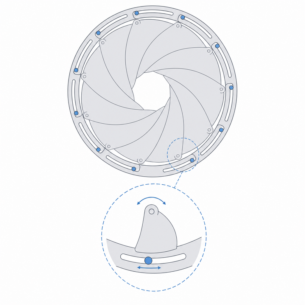
Each blade has two anchor points with opposite jobs. One is a pin fixed to the base: the blade pivots freely on it, but that point never moves. The other is a follower that lives inside a slot in the drive ring, the hoop you turn with your fingers. When you rotate the ring, its slot drags the follower; but because the first point is anchored to the base, the blade can't follow that drag with a free translation: it has to rotate about its fixed pin. The ring sends an input, the pin converts it into rotation, and the blade sweeps.
Here's the detail that almost always gets told wrong. The follower does not trace an arc around the center of the iris. It's constrained by two things at once: the fixed pin, which forces it to move along an arc centered on that pin with a radius equal to the pin-to-follower distance; and the ring slot, which does turn about the center of the iris. Those two loci don't coincide, and the slot exists precisely to reconcile them: it's radial, so that the follower can slide along it — moving toward or away from the iris center — while the blade traces its own arc about the pin. Without that radial freedom the mechanism would lock; with it, a turn of the ring is shared equally across every blade.
And it's shared because they're all identical and distributed in rotational symmetry — six blades spaced 60° apart, eight at 45° — each with its pin and its follower in the same relative positions. That angular spacing is just the mounting layout, not the blade's travel: to go from open to closed, each blade rotates about its pin a good deal less, on the order of twenty to forty degrees. The inner edge of each blade advances toward the center or withdraws, and the contour their edges leave is the aperture: never a perfect circle, but a curved polygon with as many sides as there are blades, always tangent. The iris is a single-degree-of-freedom mechanism — one input, the ring angle; one output, the hole diameter. Everything else is fixed by the geometry.
The edge curve and the placement of the two points
The whole function lives in three geometric decisions per blade: where the fixed pivot lands, where the slot follower lands, and what curve the inner edge that defines the hole has. Those three facts, plus the number of blades, set the aperture range and how close it gets to closed.
The inner edge can't be a straight line or just any arc. As the blade rotates about its pin, that edge has to stay tangent to the desired hole at every intermediate position, not only at the extremes. Trace the curve badly and two opposite failures appear, both of which ruin the mechanism. One: the hole won't close — the blades cross leaving a star-shaped gap in the center because their edges never fully overlap in the closed position. Two: the blades collide with each other before completing the travel — the edge of one invades the body of its neighbor and the ring jams halfway through the turn, or worse, forces and cracks a blade at its thinnest section. The window between "won't close" and "collide" is narrow, and it's where you find out whether you have an iris or a sculpture that turns half a revolution and binds.
It's worth being honest about closing. In printed plastic, full optical closure is nearly unreachable: the edge rounding imposed by the bead width — 0.4 mm or more — the clearance between blades, and the slightest warp almost always leave a tiny star-shaped hole in the center. The realistic goal isn't "perfect closure" but "nearly closed"; full closure only comes from a generous overlap that sacrifices maximum aperture, or from some post-processing.
The placement of the two points governs the mechanical advantage, and it's worth reasoning about it as a two-arm lever: the input arm runs from the pivot to the follower, the output arm from the pivot to the active edge. What decides the force isn't the pivot-to-follower distance on its own, but the ratio between those two arms. A long input arm against a short output arm gears it down: you need less torque at the ring to move the edge, but in exchange the ring has to turn more for a given sweep. Shorten it and the opposite happens — less ring travel, more force at your fingers — and on top of that you become more sensitive to pin clearance, because every tenth of play at the pivot is amplified at the edge. It's the classic lever trade-off, applied blade by blade.
Clearance: an iris lives or dies in the tenths between blades
This is where FDM collects its toll. An iris is many thin parts sliding against one another and pivoting on tiny pins, and each of those interfaces needs its gap. It isn't one fit: it's a dozen fits that all have to work at the same time.
At the pins — the fixed pivot and the follower — you want a free-rotation clearance, not a snug sliding one: the blade turns constantly and under side load, so any tightness translates into a hard spot you feel across the whole ring. You're at the high end of the clearance table, around two or three tenths per side, knowing the printer has already eaten part of that before you tune anything — the hole comes out narrow and the pin fat, the usual dimensional shift detailed in Tolerances for moving parts. If you model the pin and its bore at the same diameter thinking "it'll turn," it won't: it'll come out seized from the factory.
The follower also has an interface of its own that the pivot doesn't share: it slides inside the slot while the blade turns. It's not just a pin in a hole, it's a pin in a slide, and that sliding face needs its clearance like all the others — similar to the pivot's, but thinking about sliding, not just rotation. If the slot comes out narrow, the follower grabs along the travel and the ring stiffens in the middle of the sweep, exactly where you least expect it.
Between blade and blade the problem is different because the contact is flat against flat, face against face, not shaft against hole. Here the enemy is the friction of the printed surfaces, rough by definition — each blade carries the imprint of the lines on its face, and the upper face stacks the pattern of the last layer on top. Design the blades thin but rigid in their plane: a blade that bows under the pressure of its neighbors stops being tangent to the hole and starts rubbing where it shouldn't. And that rigidity comes from the print orientation.
The vertical stack: thickness grows blade by blade
There's a trap that doesn't show up until you count the blades. Because they overlap, the iris isn't flat: in the zone where several stack on top of one another, the total thickness is the sum of their thicknesses. With six 1 mm blades you have, at the worst overlap, several millimeters of stacked thickness, and that stepped packet has to turn without rubbing against the base below or the cover above.
This forces you to budget vertical clearance, and the balance is just as delicate as the lateral one. The key is to measure it against the maximum-overlap dimension, not against a single blade: what has to fit under the cover is the tallest column in the stack. Too much gap and the blades ride over one another in a disorderly way, overlap badly, jam, or one tucks under its neighbor and locks the assembly. Too little and the whole packet rubs against the covers, and the friction of so many stacked faces adds up until the ring won't turn. The healthy split is to give each blade the thickness its rigidity demands, keep them as thin as they can be without bowing, and close the sandwich with a cover or ring that keeps them coplanar without clamping them: one that guides them in their plane, not one that presses them.
| Interface | Clearance | Why |
|---|---|---|
| Pin in its bore (pivot and follower) | 0.20–0.30 mm | turns free under side load, no hard spot |
| Follower inside the slot | 0.20–0.30 mm | slides radially without grabbing along the travel |
| Blade face against blade face | just-touching (no clearance) | minimizes the friction of the overlapping stack |
| Vertical play of the packet (max stack to cover) | 0.25–0.40 mm over the maximum-overlap dimension | neither rides over disorderly nor rubs the covers |
The blade faces don't come out smooth: you print with the texture of the lines and, on the top face, with the pattern of the last layer. If you want to minimize the friction of the stack, iron them (ironing on the top face, extra top layers for a tighter skin) or accept the roughness and compensate it with a dry lubricant, powdered graphite or PTFE. Don't chase a polished finish that FDM won't give you out of the box; chase an acceptable slide.
The pins are the long-term weak point. Printed in plastic and turning constantly under load, the pin-bore pair wears: whichever of the two is weaker gives way — the thin pin or the bore, depending on material and section — the joint goes oval, the blade starts to have play, the iris loses precision, and eventually a blade drops out of its travel. If the iris is going to see real use and not just make a demo, that's where a metal pin or an embedded bushing transforms the mechanism's service life, as covered in Embedded hardware: magnets, bearings, and inserts.
Travel stops: the ring needs limits
There's one piece missing that isn't blade geometry but assembly safety: the ring has to have physical stops at both ends of the turn. In the closed position, nothing on its own stops you from forcing the ring past the point of maximum overlap; if you do, the blades cross, ride over one another outside their valid travel, and bind or crack. In the maximum-open position the symmetric thing happens: past a certain angle, the edges start to pull away from their tangency and the mechanism stops making sense. A pair of bosses that limit the ring's turn between those two extremes keep the iris always within its kinematic range, and turn the failure mode "I forced it and it bound" into a firm stop the ring simply runs up against.
The static version and the pivoting one: start with the easy one
There are two irises, and it's worth knowing which one you're getting into. The static variant is a pattern of fixed blades, frozen at a specific aperture, with no pins, no slots, nothing that moves. It's straightforward to print and works wonderfully to validate the geometry: print it in the closed position and check whether the blades really close the center; print it open and measure the hole. If the edge trace is wrong, you'll see it here, in cheap solid plastic, before you wrestle with the mechanism.
The pivoting version — the one that really opens and closes as you turn the ring — is the true engineering challenge: the complete mechanism of pins, slots, drive ring, and cover, with all its clearances coexisting. It's one of the emblematic mechanisms precisely because it brings together everything that's hard about kinematics in FDM in a single part: many sliding interfaces, a stack that grows, pins that wear, and a geometry that doesn't forgive a tracing error. When it works, it's the most striking demonstration you can put on a table that a compound mechanism fits inside a home printer.
When is it worth it? For a real diaphragm that regulates a passage of light or air, for a variable-aperture cover, or as a demonstration of a compound mechanism when you want to show what a printer can do. In every case, the iris is an exam in tolerances before it's one in geometry: master the tenths between blades and the vertical play of the stack, and the rest is tracing a curve well. And that starts with measuring your own machine, the starting point of Tolerances for moving parts.