Holes, pegs and first-layer squish
A printed hole is almost never the size you drew. Model a clean Ø5 mm hole, print it, and your Ø5 mm pin won't fit — the hole came out closer to Ø4.8. This isn't your printer being bad; it's a handful of systematic, predictable errors baked into how FDM lays plastic down. The good news about systematic errors is that you can compensate for them in the model once you understand where each one comes from.
Elephant's foot: the first layer bulges
The very first layer is squashed against the bed harder than the rest, partly to make it stick and partly because the nozzle starts close. That squish makes the bottom edge of every part bulge outward by a few tenths of a millimetre — the elephant's foot.
It bites fits in two ways. A peg printed standing up gets fatter at its base, so it jams in the first millimetre of its hole. A box printed open-side-up has its bottom outline grow, so a lid sized to the nominal walls suddenly won't slide on. The first layer of a hole, likewise, closes in.
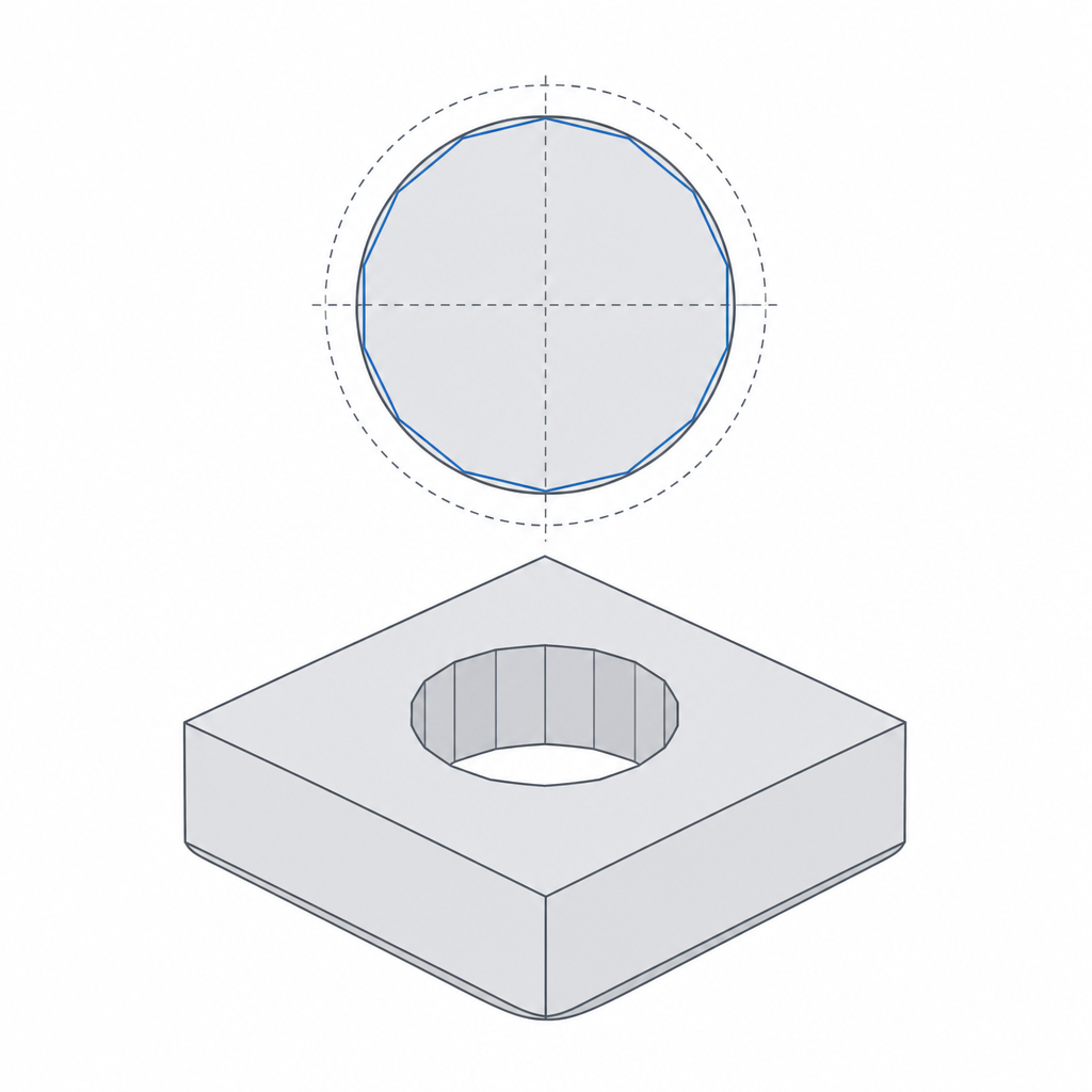
Hole shrinkage: the chord effect
Vertical holes — axis pointing up, drawn as the nozzle traces a circle — come out undersized, and the reason is geometric. The slicer approximates a circle with a series of short straight segments (chords). Every chord cuts across the true circle, sitting slightly inside it. The plastic follows those chords, so the real hole is a small polygon inscribed within your nominal circle. The smaller the hole, the worse the proportional loss.
On top of that, the inner wall of the hole bulges inward as the bead cools and the next layer presses down. Both effects shrink the opening, typically by 0.1–0.3 mm on diameter.
The fix is to oversize vertical holes in the model: add 0.1–0.2 mm to the diameter of small holes (under ~6 mm), or just design the clearance in from the start using the numbers in Real-world printed clearances. For a hole that must end up exactly on size — a bearing seat, a reamed dowel hole — print it slightly undersize on purpose and drill or ream it to final dimension.
Horizontal holes droop out of round
A hole printed with its axis horizontal has a different problem. Its top arc is an unsupported overhang — the layers spanning the ceiling of the hole sag inward because there's nothing under them. The result is a hole that's round at the bottom and squashed at the top, and often a rough, drooping crown.
The classic fix is to reshape the hole into a teardrop: extend the top of the circle into a self-supporting point at roughly 45°, so every layer rests on the one below and nothing has to bridge a flat ceiling. This is the same bridging-and-overhang logic covered in Supports and bridging — a horizontal hole is just an internal overhang you can design away. Where you can, though, the better answer is to reorient the part so the hole prints vertically and the problem never arises.
| Error | Where it bites | Design fix |
|---|---|---|
| Elephant's foot | bottom edge of pegs, walls, holes | 0.4–0.6 mm bottom chamfer |
| Hole shrinkage (chord) | small vertical holes | oversize Ø by 0.1–0.2 mm, or ream to size |
| Horizontal-hole droop | holes on a side wall | teardrop the top, or reorient |
Put it together
None of these are random. The first layer is over-squished, vertical circles inscribe inside your nominal, and horizontal ceilings droop. Add a bottom chamfer, oversize small vertical holes, teardrop or reorient horizontal ones, and your holes and pegs land where you drew them — which is the whole point, because every clearance you budget downstream assumes the parts came out the size you designed.