Worm drive: high reduction and self-locking
One drive does two things at once that no other single stage can combine: it delivers enormous reduction—fifty to one, eighty to one, in a single mesh—and it refuses to turn backward. You push on the input and the output moves slowly and with force; you push on the output and nothing happens: the drive locks up. That second property, self-locking, is why a worm holds a blind, an antenna, or an arm in place with no brake, no ratchet, and no effort on your part. And it all comes out of the geometry of a screw meshing with a wheel, not from any added part. The catch is that the two things don't come together for free: high reduction tends toward self-locking precisely because both ask for the same thing—a shallow helix that rubs a lot. You pay for it in efficiency and in heat, and in plastic the cost is higher than it looks.
A screw that drives a wheel
The kinematics of the worm drive are those of a thread pushing on teeth. The worm is literally a screw: a helix cut onto a cylinder. The worm wheel is a toothed wheel whose teeth mesh with that helix, with the axes crossed at 90°. When the worm makes one full turn, the helix advances axially by exactly one thread, and that advance pushes the wheel to turn exactly one tooth, if the worm has a single start. With a multi-start worm, one turn advances the wheel by as many teeth as it has starts: two starts, two teeth per turn. That's where the reduction comes from: for every turn of the input, the output advances a few of the wheel's many teeth.
That gives a clean, very high transmission ratio: it's the number of teeth on the wheel divided by the number of starts on the worm. A 60-tooth wheel with a single-start worm reduces 60
in one stage. To get the same with spur gears you'd need two or three stages chained together, with their shafts, their bearings, and their bulk. The worm packs it all into a single compact, crossed pair. The number of starts—how many independent helices the screw carries cut into it: one, two, three—is the lever you use to set the reduction and—as you'll see in a moment—the one that also decides whether the drive locks or not.Self-locking is a question of angles, not force
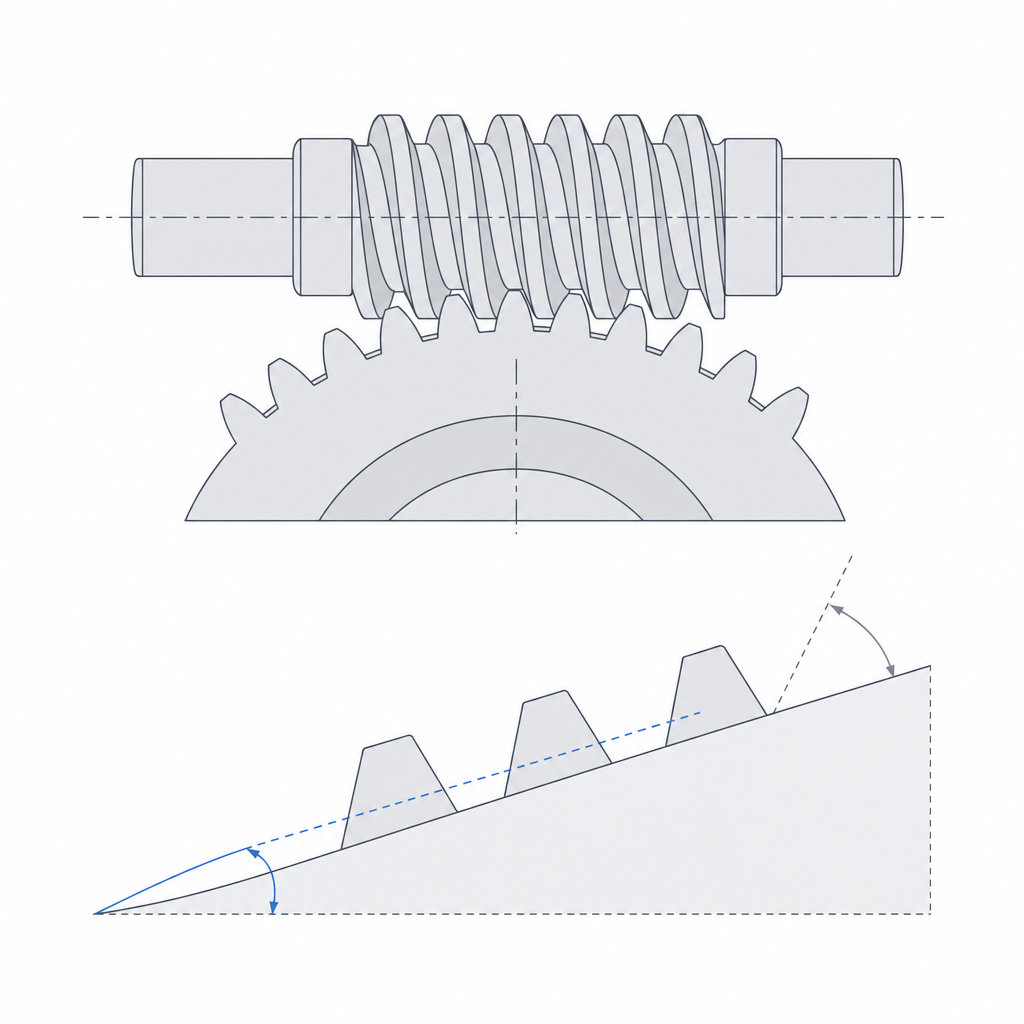
Self-locking is what makes this mechanism special, and it's worth understanding where it comes from, because it's neither magic nor mere friction: it's a contest between two angles. The first is the worm's lead angle, how inclined the helix is relative to the plane perpendicular to its axis—a very shallow helix has a small lead angle; a very steep one, a large angle. The second is the friction angle, which is simply the arctangent of the coefficient of friction between the worm and the wheel.
The rule is direct: if the lead angle is smaller than the friction angle, the wheel cannot turn the worm. Physically, the reason is this: when you push from the wheel, the force on the tooth flank resolves into a component that would tend to roll the worm and another that crushes it against the flank. With a shallow helix, the component pushing it to turn is so small that the friction of the contact itself absorbs it entirely before anything moves. The drive jams itself. It doesn't back-drive under load, and that's why it holds position without needing a brake: the worm is both motor and latch.
What lead angle do you need? As a threshold, static self-locking appears below about 5°—with margin to spare—because plastic's coefficient of friction is high—on the order of 0.2 to 0.4 against the 0.1 to 0.15 of a metal pair—and that raises the friction angle and gives you a more generous threshold. The trade-off is that this same high friction is what generates the heat. And there's another: a multi-start worm has, for the same diameter, a larger lead angle—the helix is steeper—so it gains efficiency and loses self-locking. It's a design decision, not an accident: if you want the output to hold load on its own, you stay at a single start and a low lead angle, accepting that the drive will be inefficient. If what you want is motion—and you add the brake separately—you go up to two or three starts and recover efficiency.
Print the worm upright and the wheel flat
This is where FDM imposes its rules. The worm is a continuous helix, and what you want is for that helix to come out as clean as possible, because any roughness on the flank multiplies a friction that is already high in this drive. The orientation that helps most is to print the worm vertical, with the screw's axis along Z: that way each layer is a nearly circular section of the helix and the contour rises continuously turn after turn, instead of being stepped as it would be if you laid it down. Printed upright, the screw also needs no supports—which would wreck the thread when peeled off.
But don't think vertical means "no steps." With the axis along Z, the layer lines sit perpendicular to the axis, and the thread flank presents that layer stepping right along the direction in which the wheel slides over it. Macroscopically the helix is continuous; microscopically, each flank carries the stair-stepping that the tooth rubs against. That's why vertical orientation is a necessary but not sufficient condition: reduce the layer height on that part and, if the torque warrants it, smooth or dress the flank. Real smoothness is something you add, not something the orientation gives you.
The wheel, by contrast, goes flat on the bed, with its axis along Z, like any toothed wheel: the teeth come out well defined in the XY plane, which is where the printer has its best resolution, and the broad, flat face seats and adheres well to the bed. This is exactly the logic developed in Layer orientation for motion: you orient each part so its functional surfaces fall where the process makes them clean and so the load doesn't pull on the bond between layers.
The underlying problem of this drive in plastic is that the worm–wheel contact is sliding, not rolling as in two spur gears. Where two spur teeth roll over each other with little sliding, the helix here rubs longitudinally against the wheel's tooth on every mesh. That continuous friction is what gives the self-locking, but it's also what generates heat and wear. And plastic is a poor candidate for two reasons: it neither dissipates heat the way metal does, nor withstands it. PLA, the default material in FDM, softens past the 55–60 °C of its glass-transition temperature, a figure frictional heat reaches easily; under sustained load it flows and deforms very fast. For a worm that's going to do real work, move up to PETG, ABS, or, better, nylon or filled nylon, which take more temperature and more friction. In a plastic worm, wear and heating are not a footnote: they're the primary failure mode, and you have to design against them from the very first sketch.
Clearance: the mesh either overheats or seizes
The worm–wheel mesh needs a fine fit, and this pair is less forgiving of clearance than almost any other, precisely because of its high friction. Follow the chain: if you tighten the mesh—axes too close together, teeth too full—the sliding contact rubs harder, and since that friction dissipates as heat, the contact zone heats up; the plastic softens near its glass transition, the tooth loses stiffness, the mesh closes even further, and you enter a loop that ends in seizing: the drive locks up not from self-locking, but because it has melted against itself.
That's why here you don't go for the tightest possible mesh, but the right gap, so the helix slides without excessive play yet without binding. And the parameter you really use to set that gap is the distance between the axes of the worm and the wheel, not the tooth thickness: you bring them closer or move them apart until the pair turns smooth and cool. The underlying reasoning—thinking about clearances side by side, allowing for the hole coming out narrow and the tooth thick—is the same as for any printed fit, as Tolerances for moving parts explains. There is also an adjustment variable that is optional in other gears and here almost mandatory: lubrication.
Here it pays to reason carefully, because it is easy to get the sign wrong. A grease suited to plastic lowers the coefficient of friction, which reduces heat and wear, which is what you want. But lowering the friction also lowers the friction angle—recall that it is its arctangent—and since self-locking requires the lead angle to stay below the friction angle, lubricating reduces the self-locking margin. On a worm right at the threshold, greasing it can be exactly what releases the lock and lets it back-drive under load. So lubricate to control the heat, but design the lead angle with enough margin below the threshold that the grease doesn't release the latch for you, or don't entrust the holding of a load to a pair that only locks when dry.
What it's good for and how it breaks
The worm is the right choice in a handful of very specific situations. The first is when you need a large, compact reduction in a single stage: what would be two or three stages with spur gears, the worm solves with a crossed pair the size of your palm. The second, and the one that truly sets it apart, is when you want the output not to be able to move the input: holding a load, keeping a position, preventing a shaft from backing off when you release the motor. If your requirement is "stay where I leave it, with no brake," the single-start worm meets it by geometry.
What you pay for it is efficiency. The self-locking worm—the single-start, low-lead-angle one—is among the least efficient gear pairs: it turns much of the energy you feed it into frictional heat, sometimes more than half. That is the flip side of self-locking, and it's worth not generalizing: a multi-start worm with a steep helix can exceed 90% and competes with any other gear. Its failure modes come out of that friction, all of them well known and all preventable. Wear and heating from the continuous sliding are the underlying deterioration, which in plastic advances fast if you don't lubricate. Stripping of the wheel—teeth sheared off or with their tips torn away—shows up when the torque exceeds what the section of the plastic tooth can take: the wheel almost always gives before the worm, because its teeth are more slender and work one at a time. That is why classic practice makes the worm from the harder material and the wheel from the softer, sacrificial one—in metal, a steel worm and a bronze wheel—so the wear concentrates on the cheap part; in FDM, the equivalent is a worm in a rigid, well-finished material and a wheel treated as a spare part. And seizing from a tight fit or lack of lubrication is the one you have already seen—the spiral of heat that ends with the pair melted and locked.
The defense against all three is the same combination: a wheel with generous, well-filled teeth to resist stripping, a fit loose enough not to overheat, real lubrication, and not asking the plastic to sustain a torque only metal would take. Designed this way, the worm offers what no other single stage does: lots of reduction, lots of torque, and an output that stays put on its own. When to lay each part down, and why the bond between layers decides whether the teeth strip or hold, is the other half of this work—you'll find it in Layer orientation for motion.