Ball joint: multi-axis articulation
A pivot gives you one axis of rotation; a ball joint gives you all of them at once. A sphere trapped in a concave socket turns in any direction from a single point, and that is exactly what you want on a camera arm, an orientable mount, or the hip of an articulated figure: point it anywhere without three hinges in series. But that freedom comes at a price, and in FDM you pay it in geometry. The ball has to enter a socket that wraps it past the equator — otherwise it won't retain — and to get in, it has to spread that socket open. The whole joint is decided in that one move: how far the rim wraps, how much it gives when the ball seats, and how much it drags afterward. Get all three right and you have a joint that stays where you put it; miss them and it either won't go in, won't hold, or comes out on the first pull.
Three degrees of freedom from a single point
The kinematics of a ball joint are those of a spherical joint: ideally, the center of the ball is a fixed point relative to the socket, and the sphere rotates freely about that center. That is three rotational degrees of freedom concentrated in a single element, against the one degree a pin pivot gives you. But the three are not equally useful for aiming. The two useful ones are pitch and yaw: they tilt the stem and set where whatever hangs off the ball points. The third, roll — the spin of the sphere about the axis of the stem itself — does not change the direction you point: it spins the arm about its own axis and, in most setups, is a parasitic degree of freedom that you neither control nor need.
Ideally, there is no translation at all: the center does not move, only the orientation changes. In a real part there is some translation, and it pays to be clear about it from the start, because it is the same phenomenon we call wobble later on: the play and elasticity of the rim let the center shift a little under load. A well-tightened ball joint reduces it to almost nothing; a loose one turns it into visible slop.
What limits the range is not the sphere; it is the neck: the stem joining the ball to the outer part runs into the rim of the socket when you tilt too far. The useful sweep angle is therefore the one between the rest position and the moment the neck hits the rim. A thin neck gives you more range; a thick neck cuts it down. Design the neck for the cone of motion you actually need, not for the theoretical maximum.
The rim retains because it wraps past the equator
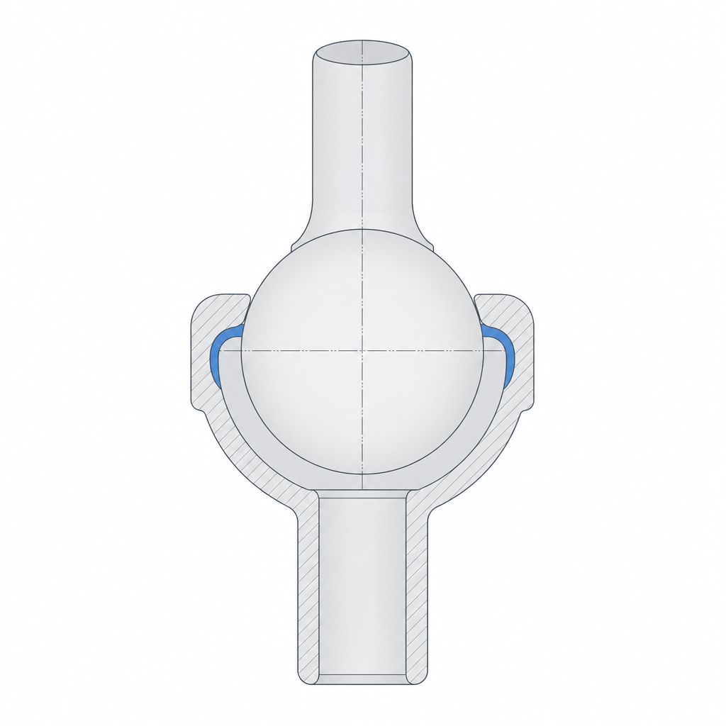
Here is the physics that makes a ball joint a ball joint and not a loose ball in a bowl. For the sphere to be captured, the socket has to close over it past the equator: wrap more than a hemisphere. If the rim of the socket stops right at the ball's maximum diameter or below it, nothing stops the sphere from pulling straight out; the socket is then a seat, not a catch. The moment the rim passes the equator, getting the ball out means deforming that lip again until the opening grows back to the sphere's diameter, and that deformation is the barrier that keeps it in.
Which means the socket is an annular snap-fit disguised as a bowl. Assembling the ball joint is exactly that: pressing it into place. The ball pushes on the retaining lip, the lip spreads until it lets the equator through, then closes behind it and traps it. Everything you know about annular snaps applies — how far the rim overlaps the ball is the equivalent of a hook's overhang, and it sets both the insertion force and the retention force at once. That is why it pays to read a ball joint with Snap-fits that won't release in mind: a rim that wraps too much won't go in without splitting, and one that wraps too little won't hold; the sweet spot is where the lip can flex enough to swallow the equator and recover afterward without yielding.
The "range versus retention" question has a better answer than trimming the wrap around the entire perimeter. Range is limited by the neck hitting the rim; retention is given by the overlap past the equator. They act in two different places: you can lower the height of the rim locally — a scallop on the side you tilt toward most — to gain sweep, without touching the equatorial wrap anywhere else on the contour. A socket with a local scallop gives you the cone of motion you ask for while retaining just as well. You don't have to trade one for the other around the whole perimeter.
Friction is what holds it in place
A camera ball joint is worthless if it turns freely: it sags under its own weight the moment you let go. What keeps it pointing is the friction torque at the ball-socket contact, and that torque has to beat the moment the weight of the arm exerts about the center of the sphere. Here the fit works the opposite way to a free joint: you are not after clearance, you are after squeeze. The ball has to enter against the socket with enough interference that the contact pressure generates the friction that holds the position.
That puts you in a fine trade-off between two opposite failures. Too tight and the ball joint seizes: it is hard to orient, and forcing it punishes the rim. Too loose and it wobbles and sags: no pressure, no friction, no position holding. The number that separates the two is a few tenths of a millimeter of interference on the diameter — on the order of 0.1–0.3 mm to start — and your printer will shift that number. That is why a ball joint is a textbook case for calibrating the fit on the real part, not the nominal: the same method as in Tolerances for moving parts, but aiming for the tight side of the scale, not the sliding side.
Here the material matters as much as the dimension. PLA is a poor candidate for retention that has to last: it flows slowly at room temperature (creep) and softens under modest heat — direct sun or the inside of a car is enough to make a PLA camera mount droop on its own. For sustained friction retention you want PETG, ABS, or nylon, or better still, two different materials: a hard, stiff ball against a slightly more flexible socket that wraps without cracking and keeps the pressure up. The same plastic against itself is what ages worst.
| What you want | Ball-socket fit | Result |
|---|---|---|
| Orient it and have it stay put | Light interference (~0.1–0.3 mm on Ø) | Retention friction; holds the arm in place |
| Pivot freely, no weight to hold | Transition or slight clearance | Turns with little effort, won't hold position |
| Too tight | Excessive interference | Seizes, punishes the rim when moving |
| Too loose | Open clearance | Wobbles and pops out; no retention |
Orienting to control the sphere's stair-stepping
A sphere is the hardest shape for FDM: the printer builds it in flat layers, so its surface comes out faceted, stepped in rings wherever each layer changes radius. On a ball joint those steps fall right in the zone that matters most, the band that rubs against the socket, and they make the rotation rough and jerky instead of smooth. The stair-stepping is worst on the near-horizontal zones of the sphere — near the poles, where the radius changes a lot per layer — and finer where the wall runs nearly vertical, around the equator.
You don't eliminate them, but orientation decides where they concentrate. Don't kid yourself with too tidy a solution here: the contact band of a ball joint is not a point, it is a wide band. A good part of the lower hemisphere carries load and the rim touches near the equator, so you can't fit all of the contact zone into the vertical part. What you can do is choose where the worst of the faceting falls: orient the ball so the most loaded band, the one that really holds the weight and that you sweep across most, lands in the most nearly vertical zone you can manage, and push the poles — where the stair-stepping is coarse — toward a region that barely sees load. It is a redistribution, not a cure: you improve one band at the expense of another, and you choose which one to sacrifice.
The socket wants the opposite of what intuition suggests. Since it is the press-fit that opens to swallow the ball, its rim must not print either fused shut or with an oversized wall: if the lip prints as an overhang, the printer closes it poorly; if it prints as a wall so thick it won't flex, assembly splits it. Orient and size the socket for what it is — a ring that has to open — and give the rim just enough thickness to retain and work in bending, no more. The ball usually prints best with as little support as possible — anything that avoids dense support stuck to the spherical surface, because that support leaves a scar right on the running track. If you split it to print it, don't cut along the equator — the seam would land right in the contact zone, the worst place for a discontinuity. Instead, take the parting plane to a pole, away from the band you sweep across.
Above all is the rule that governs any part that flexes: the rim of the socket works in bending every time you snap the ball in, so its layers can't be oriented so that the flexing pulls them apart. A rim printed on edge, with the layer line perpendicular to the direction it has to open in, delaminates on the first assembly instead of flexing. It is the same principle that governs everything that bends in an FDM part, developed in Layer orientation for motion: orient the contour of the socket so the rim flexes along the beads, not between layers.
How it fails, and how to prevent it
A printed ball joint fails in three ways, and all three are headed off at design time. The first is that the ball pops out of the socket: the rim retained too little — it didn't wrap well past the equator, or it was too thin to keep the opening closed — and an axial pull frees it. You fix it by giving the rim more overlap on the ball, as much as still lets you assemble it, or with the local scallop that buys sweep without sacrificing wrap.
The second is seizing and wear from the stair-stepping: the contact between the faceted sphere and the socket is not smooth, it scrapes, and with use those steps file down, leaving play where there used to be squeeze. You mitigate it with the orientation we have seen, but the cheapest fix is in the making, not the design: break the joint in by cycling the motion a few times so it beds in, work a touch of dry lubricant or PTFE grease into the contact, and if rotation quality truly matters, lightly sand or polish the ball before assembling it. In practice it's the first thing you do with an orientable mount, and it solves more than any dimensional tweak.
The third is the loss of retention friction over time, and it pays to separate two distinct causes because they have distinct remedies. One is wear: the surface polishes and leaves play, which we have already covered. The other is rim relaxation: the lip, which sits permanently flexed and preloaded against the ball, loses that preload over months through creep — it takes a permanent set and stops pushing. The first you slow with harder material and careful break-in; the second by choosing a plastic not prone to creep and designing so the rim isn't over-stressed at rest. When the joint has to hold a considerable weight for a long time, assume the printed ball joint is for orienting, not for supporting: there, a well-measured clearance counts as much as in any other joint, and your starting point is in Tolerances for moving parts.