Scissor and lazy tongs: a lot of extension from very little
Squeeze together one end of a chain of crossed X-links and the far end shoots away: a few millimeters of input become a hand-span of output. That is what makes the scissor mechanism—and its stretched-out cousin, the lazy tongs—so fascinating, and what makes it treacherous in FDM. Because that same chain that multiplies travel also multiplies—joint by joint—every tenth of a millimeter of play in the pins. The mechanism that impresses most on screen is the one that forgives a loose tolerance least, and it pays to understand why before you print a twelve-link chain that comes off the bed with a wobble.
One X is already a lever; chaining them multiplies it
The basic building block is two straight links crossed and pivoting where they meet, like the blades of a pair of scissors. Bring the two ends on one side together and the two ends on the other side spread apart. So far it is a lever: the central pivot is the fulcrum, and the ratio between what goes in through one pair of tips and what comes out through the other depends on where that crossing falls along the links.
What turns a lever into an amplifier is chaining several X-cells in series, sharing pins between the ends of one cell and those of the next. Each X adds its own extension to the previous one, and because they all open at once, governed by the same motion, the travels add up. A small input at the first pair produces an enormous output at the last—geometric amplification of displacement, pure kinematics, with no gears or pulleys. The more X-cells, the more extension per millimeter of input.
And here is the law that governs the whole mechanism and cannot be evaded: what you gain in travel you lose in force, in exactly the same proportion. This is not an implementation detail; it is conservation of energy. If you multiply displacement by ten, the output force is one-tenth of the input (less, once you count friction). The scissor does not create work; it only redistributes it. Design it knowing you are buying travel with force, and decide in advance which of the two you can spare: travel or force.
The mechanical advantage lives in the scissor angle
The ratio between the force you put in and the force you get out is not constant over the deployment: it changes with the angle between the crossed links, and that change is what makes or breaks a scissor lift. It helps to separate two things that are easy to mix up: the abstract kinematics of the X, and the concrete geometry of the actuator that drives it.
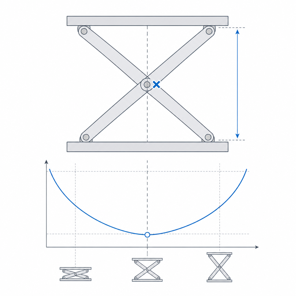
Define the angle as that between each link and the axis along which the chain deploys. With the scissor nearly closed (folded), the links lie almost parallel to that axis, a small angle; as it opens, the angle grows toward 90°; fully extended, the two links of each X become nearly collinear. The mechanism's input-output ratio varies with that angle—opening from folded is not the same as finishing the final stretch.
What really decides the sizing is where the concrete actuator sees its worst mechanical advantage, and that depends on how you push. In the usual case—a scissor lift with the actuator nearly horizontal at the base—the worst deal is at the bottom, with the scissor closed: there the actuator pulls almost parallel to the motion it has to produce, its lever arm is minimal, and it needs an enormous force to lift the load off the ground. This is the classic, well-known problem of scissor lifts: the drive force is greatest right at lift-off, not at the end. As the chain rises and the links straighten, the actuator gains angle and the force you ask of it drops. That is why a lift that struggles to start then climbs the rest of the way with ease: size the drive for the worst case—the start from closed—not for the easy stretch near the top.
Clearances don't just add up: they accumulate and amplify
This is where the scissor charges you in FDM for what it promised in kinematics. Each pin has its clearance—the gap between axle and hole that it needs in order to turn—and in an isolated pivot that tenth of a millimeter is harmless. In a chain it is not. The play of each joint propagates along the whole series, just as the useful displacement does. The chain does not distinguish between the motion you want and the wobble you do not: it amplifies both equally.
A simple model helps here, because the effect is neither a plain sum nor an arbitrary product. Each joint contributes a small angular play: the link can rotate a few thousandths of a turn within its clearance before it makes contact. Those angular contributions add up along the series, roughly linearly with the number of joints. And that accumulated angular error is amplified by the length of the deployed chain: the same half-degree of uncertainty at the base becomes a wobble that grows with distance to the tip—and the tip travels farther out as the chain opens. The net result is a mechanism that grows looser as it extends: with the scissor closed the assembly seems firm; as it opens, the play adds up and the amplification arm grows, and the tip of the last link ends up trembling by millimeters even though each individual joint had only a few tenths of play.
The defense is straightforward but demanding: tighten the per-joint tolerance more than you would in a standalone pivot, because here the error accumulates and amplifies. Aim for the finest sliding fit your printer can achieve without seizing—measure it, don't guess, using the method in Tolerances for moving parts—and apply it to every pin in the chain. And because all the joints are in series, the seizing accumulates too: a fit so tight that you'd feel it only as drag in a single pivot becomes, across twelve joints, a chain that will not move. That is the other side of the problem, and the one that sets the practical limit on how many X-cells you can chain.
Series friction limits how many X-cells you can chain
Backlash isn't the only thing that accumulates joint by joint; friction does too. Each turning pin contributes its friction torque, and in a chain of twelve plastic-on-plastic joints those torques add up and the drive carries all of them. That has a consequence that shows up right where you have the least margin: near full extension, the mechanism's output force is already minimal by pure kinematics, and on top of that the actuator is fighting the accumulated friction of the entire series. There comes a number of cells at which the summed friction eats the little push that remains, and the chain stalls or moves in jerks even though no joint is seized on its own.
That is why the useful number of X-cells isn't set by wobble alone: it is also set by series friction. If you need many cells, consider metal axles at the joints to lower the per-pin friction, reduce the number of plastic-on-plastic joints, or accept that the chain works well at deploying but won't deliver fine force at the end. Count that accumulated friction in the drive's force budget, not the payload alone.
Lateral buckling vs. link buckling: two distinct failures
A long scissor chain has two ways of collapsing, and it pays not to confuse them, because they are fixed differently.
The first is lateral buckling of the assembly: the chain, loose from the accumulated clearances, twists out of its working plane. It is meant to move in a plane—opening and closing the X—but the play of the pins leaves it an out-of-plane degree of freedom it shouldn't have, and under any lateral load or its own weight the chain bows sideways. The longer and more extended the chain, the worse this becomes. The fundamental defense is the same as before—tightening the clearances—but when the chain is very long that isn't enough, and then you have to guide it laterally: a rail, a slot, or a pair of guides that capture the ends and restrain that out-of-plane degree of freedom by geometry, not by friction. That is what a real scissor lift does with its guides at the base.
The second is buckling of the links in compression, and it is a failure of the link, not of the chain. When the mechanism transmits load, many links work in compression along their axis, and the links of a scissor are long and slender by design. A slender column in compression doesn't fail by crushing: it buckles, arching suddenly at the middle when the load exceeds its critical limit. In the slender, elastic regime that limit falls with the square of the length—a link twice as long buckles at a quarter of the load—but be careful applying the formula blindly: in a scissor the links rarely work as a pure column, because the central pivot loads them at an intermediate point and introduces bending, and in short, thick FDM parts, the dominant failure is not elastic buckling but bending or delamination between layers. The square law governs when the link is genuinely slender; in short links what governs is the strength of the section and of the bond between beads.
In both cases the print orientation is decisive: print the links lying flat in the bed's XY plane, with their wide section resisting the bending and the layers running along the link, not stacked across it. A flat-lying link is a solid beam in the direction that matters; one printed on edge adds inter-layer weakness to its slenderness and buckles or delaminates far sooner. It's the logic developed in Layer orientation for motion, applied to a part that works as a column.
Reinforce the center, slow wear, control play
Three details remain that separate a scissor that lasts from one that loosens the first time you show it off, and all three run into a decision you have to make first: how you build the joints.
There are two routes, and they do not mix freely. One is all print-in-place: the joints come off the bed already closed, with nothing to insert, convenient and fast but locked into plastic on plastic. The other is loose links plus axles: you print the pieces separately and assemble them with pins—printed or metal—more assembly work but with far better joints where they load most. Decide the route before you design the joint, because almost everything that follows depends on it.
The central pivot carries more. In each X, the central crossing is the fulcrum of the lever, and the reactions of both arms pass through it. Not every pin sees the same force: the central ones and those closest to the drive work harder than the free tips. Reinforce them—larger pin diameter, more material around the hole, or a metal axle embedded in the most loaded joints—instead of building the whole chain with the same flimsy joint. A central joint that ovalizes its hole under load reintroduces play right where it amplifies most. And here a trade-off with orientation appears: lying the link flat is best for its stiffness, but it leaves the pin's axis vertical (Z), so the radial load on the hole pushes between layers, the weak direction, exactly the one that ovalizes. In the heavily loaded joints, that is the concrete reason to put in a metal axle: the link's optimal orientation leaves the printed hole in its worst direction, and the metal gets you out of that trade-off.
Wear is spread across many pins. A scissor has a great many pins turning, and if they are all plastic on plastic, they all wear at once. Each joint that loses material gains play, and you already know what play does to a chain. For a mechanism that will cycle a lot, consider metal axles at the joints, or at least at the central ones; plastic on plastic is fine for an occasional deployment, not for a thousand cycles.
You fight play by tightening, not by compensating for it. There is no geometric trick that removes the accumulated play of a long chain; the only real lever is the per-joint tolerance. Tighten every pin to the limit of free rotation, reinforce the central ones, guide the ends of long chains, and print the links flat. With that, the scissor delivers its spectacular effect—a lot of extension from very little—without the wobble that gives away a poorly calibrated chain.
If you're going to carry that precision into a chain of many joints, the next step is to dial your printer in to its finest, most repeatable sliding fit, and to carry that number, joint by joint, across the whole chain. Start with Tolerances for moving parts.