Rigid shaft coupling (sleeve or flange): joining aligned shafts
A rigid coupling joins two coaxial shafts so they turn as one, with no degree of freedom between them: a sleeve that grips both shaft ends and locks them with set screws, or two flanges bolted face to face. It's the simplest way to transmit torque, and also the most demanding. Nothing in it absorbs error: every tenth of a degree of misalignment you impose passes straight through, undamped, to the bearings that carry the shafts. In metal, that's a matter of careful assembly. In FDM, it's also a matter of how you grip a smooth shaft with a plastic part without it slipping, and how you tighten a screw against a thread you printed yourself.
Rigid means the bearings pay for the misalignment
The whole point of a rigid coupling is torsional stiffness: it locks both shafts together and transmits torque without giving an inch, with zero backlash. Turn one end and the other turns exactly the same amount at exactly the same instant. That's its virtue and its trap, because the same stiffness that kills the backlash also kills any tolerance for misalignment.
Think about the kinematics of two shafts that aren't perfectly coaxial. If there's a small angle between them — angular misalignment — or a lateral offset between their centerlines — parallel misalignment — a rigid coupling forces them to turn as a single solid. But those shafts are held by bearings that expect to spin about a fixed line. Forcing coaxiality where there is none turns the rotation into a bending load that repeats once per revolution: the coupling forces each shaft to flex against its bearing, and that radial load rotates with the shaft. The result is vibration at running frequency, heating, and premature bearing wear; the bearings fail under a load in a direction they were never designed for.
Hence the rule that governs everything else: a rigid coupling only works with shafts that are already well aligned. It doesn't correct; it transmits. You want it when you split a long shaft into printable sections and need the assembly to behave like a single bar, or when you extend a shaft without losing stiffness or introducing play. The moment you suspect there will be misalignment — loose assembly tolerances, supports that don't share a plane, thermal expansion — drop the rigid coupling and move to a flexible coupling, an Oldham, or a jaw coupling, which exists precisely to absorb that error without dumping it onto the bearings.
Torque enters through the shaft: a smooth grip slips
The weak point of a printed rigid coupling isn't the body of the sleeve, which has section to spare. It's how torque gets from the shaft to the hub. A round, smooth shaft is held only by friction, and the friction a set screw can generate against a polished cylindrical surface is negligible next to the torque you intend to transmit. In FDM, moreover, the limit isn't the set screw but what holds it: the plastic of the hub gives way before the screw clamps hard enough. It then fails in one of two ways, neither good: either the shaft slips inside the sleeve from the first attempt while the other end stays put, or the set screw locally deforms the plastic hub and the grip loosens with use. The steel shaft is unaffected; the printed part is what gives way.
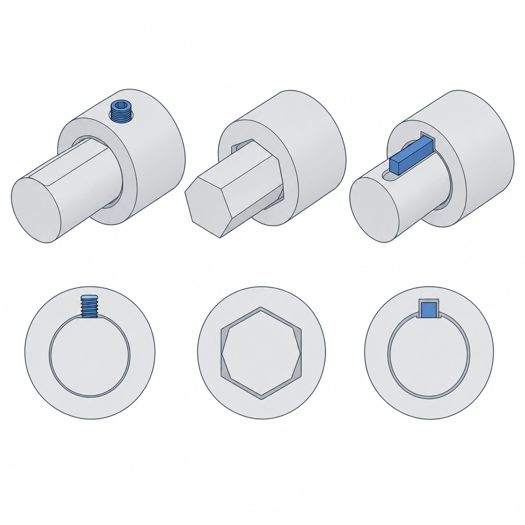
The fix is to stop trusting torque to friction. Give the contact a shape that blocks rotation by geometry, not by clamping force:
- A set screw against a flat machined or filed into the shaft. The flat turns the contact from tangential to normal: the set screw no longer has to keep the shaft from turning through friction, it bears against a plane that stops it. It's the minimal fix and almost always enough.
- A non-round shaft — hex or square — with a matching socket. Here the anti-rotation is the section itself: the corners bear against the faces of the hub, and nothing can slip without shearing. It's also the option that suits FDM best, because a hex hole prints as easily as a round one and spreads the contact over lines rather than around a ring, the same load-sharing principle explained in Interference without cracking.
- A keyway, a slot in shaft and hub with a key locking them together. It's the standard in serious metal drives, but note that in plastic it's the most fragile of the three. The key works in shear across its section, but the printed keyway fails much sooner by crushing of the flank: a thin wall, anisotropic between layers, takes the full torque load. If you use it, make the key metal and reinforce the hub flank with material; if you can avoid it, avoid it.
The hierarchy is clear: if you can choose the shape of the shaft, make it non-round and forget the problem. If the shaft is given and it's round and smooth, file a flat and aim the set screw at it. Trusting torque to a set screw against a polished cylinder is building the slip in.
The set screw needs a real thread
Even if geometry blocks the rotation, there's still a screw doing the clamping, and that screw needs to thread into something. Here's the second classic failure of the printed coupling: a small printed thread won't survive repeated tightening. Plastic threads come out coarse, the profile rounded off by the bead width, and the tightening torque you need for the set screw to bite strips those threads in a handful of assemblies. The smaller the diameter — M2, M3, M4 — the sooner it happens, because there's less thread area to sacrifice; going up a couple of millimeters delays it but doesn't solve it. The first time it grips; by the third it spins free.
Plan from the model for a threaded insert — the kind that seats hot, melting the wall around it — or a captive nut housed in a hex pocket where the screw threads into metal, not plastic. The metal takes the tightening the set screw demands, assembly after assembly, without stripping. How to size the insert or nut pocket, and why the printed thread doesn't measure up, is in Threads, inserts, and nuts; the practice of embedding that metal in the part, in Embedded hardware: magnets, bearings, and inserts.
Orient the sleeve's print with the hole axis vertical, perpendicular to the bed. A hole printed vertically comes out round and to predictable tolerance; laid down it comes out oval and sagged on the top face from the overhang, and stops gripping the shaft concentrically — exactly the opposite of what a coupling needs.
The bolted flange: torque across many bolts, disassembly without unseating
The alternative to the sleeve is the two-flange version, each flange keyed to its shaft and bolted face to face by a ring of bolts. It has two advantages over the sleeve. The first is that it spreads the torque across several bolts instead of trusting it all to one set screw: in a well-made joint, the bolt preload generates friction between the two faces, and it's that friction that transmits the torque, with a lever arm equal to the radius of the bolt circle. The second is that it disassembles cleanly by removing the bolts, without having to pull the coupling off the shaft.
The problem in plastic is that this face-to-face friction doesn't hold: the material flows under the bolt preload — creep — and the joint loses clamping over time and temperature. As soon as the friction drops, the joint slides until each bolt bears against the wall of its hole, and from there the torque is carried by the bolt in shear and crushing. That's the real failure mode of the printed flange: the torque pulls each bolt tangentially, that force unloads onto the wall of the hole, and if the bolt circle is small or the wall between the hole and the edge of the flange is thin, the bolt shears the plastic and breaks out at the edge, tearing off a tab. Size the bolt circle with a generous radius — lowering the force each bolt sees — and leave plenty of material between each hole and the contour. And remember that the torque still has to get from each shaft to its flange: the sleeve's anti-rotation problem doesn't disappear; it just moves to the shaft-hub interface of each half-flange, where the same remedies apply: a flat, a non-round shaft, or, in the last resort, a reinforced keyway.
| Decision | Recommendation | Why |
|---|---|---|
| Shaft-hub anti-rotation | Flat or hex/square shaft | A smooth set screw's friction slips |
| Axial retention | Stop: shoulder, ring, or set screw in a dimple | Anti-rotation doesn't stop the shaft sliding out |
| Set screw thread | Threaded insert or captive nut | A small printed thread strips with repeated tightening |
| Orientation | Hole axis vertical | A round, concentric hole, not oval |
| Flange: bolt circle | Wide radius, thick wall to the edge | Creep loses the friction and the bolt goes into shear |
| If there's misalignment | Switch to a flexible coupling | The rigid one forwards it to the bearings |
Concentricity: if the two seats don't share an axis, it vibrates
There's one failure left that comes not from torque but from the geometry of the coupling itself. A sleeve has two bores, one for each shaft, and the part only does its job if those two holes are rigorously concentric: they share a single centerline. If they come out of the printer off-center relative to each other — even by tenths of a millimeter — the coupling imposes a fixed eccentricity on the shafts. The assembly turns with its center of mass off the axis of rotation, and that is, by definition, imbalance: vibration at running frequency, identical in symptom to misalignment, only manufactured by the part itself.
The defense is in the print. Printing the sleeve as a single piece and vertically, with both holes sharing the same model axis, is the best your machine can do — as long as its Z axis is straight and square to the bed; a leaning gantry or an out-of-square Z throws the two seats off-center precisely when you print vertically. The slicer doesn't guarantee that concentricity between seats, and so, if the tolerance off the bed isn't enough for the speed it's going to spin at, don't keep fighting it in the slicer: ream the holes to size — run them with a reamer at the final diameter for finish, or bore them referenced to a single setup if the axis needs correcting — and let metal, not the printed bead, set the concentricity. A drill bit won't do here: it follows the existing hole, wanders, and leaves an imprecise diameter.
The catalog of failure modes for a printed rigid coupling comes down to five, all covered above: the set screw that slips on a round, smooth shaft; the set screw thread that strips after a few tightenings; the slow loosening from creep in the plastic under sustained clamping; the flange that shears under torque in weak holes; and the vibration, whether from poor manufacturing concentricity or from a misalignment you imposed yourself on bearings that can't absorb it. Design it knowing where each one comes from, and the coupling will do the one thing it's asked to: make two shafts turn as one.
When the torque you're about to transmit starts to depend on a screw tightened against the shaft, it pays to be clear on the mechanics of the thread and the clamping: Threads, inserts, and nuts is the logical next step.