Embedded bushing and bearing: let the bearing spin, not the plastic
There comes a point where plastic spinning against plastic stops being good enough. A printed peg turning inside its printed hole works, but with a breakaway torque you can feel — it scrapes, heats up, and above all wears. Every revolution shaves off a few microns of extrusion: the hole opens up, and after a few hours of service the fit you calibrated so carefully is no longer the one you started with. For a hinge you open twice a day, that doesn't matter. For a wheel, a pulley, or a shaft that turns thousands of times, it does. That's where you stop asking the plastic to be the running surface and hand the job to a part built to spin: a bronze or PTFE bushing, or a ball bearing, seated inside the printed part. The print stops being the bearing and becomes only the support that holds it. Everything then comes down to one thing: how that seat is dimensioned.
Why plastic makes a bad bearing surface
Plastic-on-plastic contact has three problems that compound. The first is high friction: PLA or PETG sliding against itself has a high friction coefficient you feel as breakaway torque, and that torque grows if the fit is a touch tight or if the printed surface is rough, which it always is — stepped, layer by layer. The second is wear: the surface of an extrusion isn't hard, so repeated rubbing polishes it and removes material. The third is the direct consequence of the second: because wear removes material, the fit changes with use. You start with a sliding clearance and end up with play, vibration, and a rotation that is no longer either precise or smooth.
A bushing or a bearing attacks all three at once, though each with its own physics. A self-lubricating sintered-bronze or PTFE bushing slides with far lower friction than plastic and resists abrasion far better; it's still a sliding contact, so it does wear, but slowly, and its life depends on load and speed, on the pressure-times-velocity product, and on keeping its lubrication. A ball bearing is in another league: it swaps sliding for rolling, which has almost no breakaway torque, and its life is counted in fatigue of the races over millions of revolutions, not in hours of rubbing. In both cases the working surface is metal or an engineering polymer, so the fit doesn't migrate the way plastic did. When rotation quality really matters, this is the best option by a wide margin.
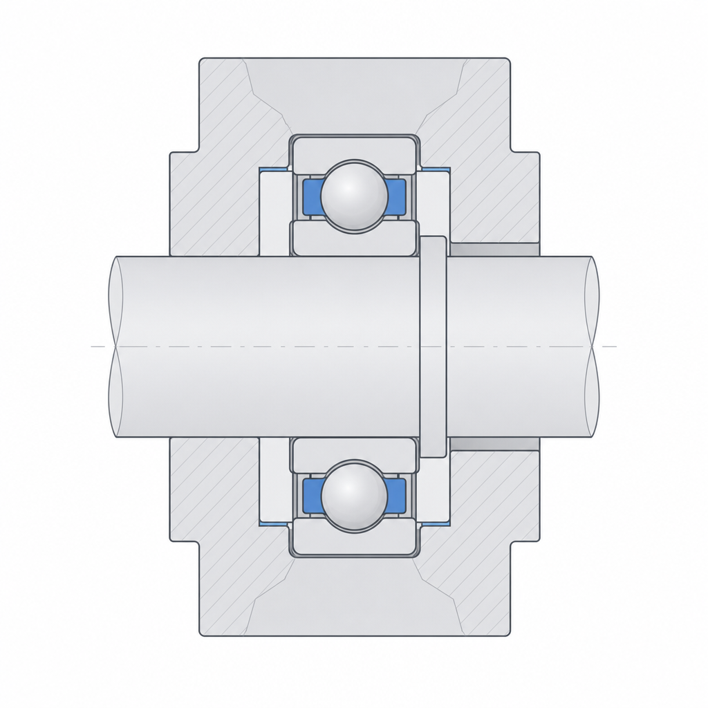
The seat holds the bearing without deforming it
Here the logic inverts. When plastic was the running surface, you sized the hole so the shaft would slide inside it: you wanted clearance. Now the plastic doesn't spin at all; what the seat — the pocket, in FDM terms — has to do is hold the bearing still. The outer ring of a bearing must not turn relative to the part. If it does, it rubs and wears the plastic, so the pocket works against that ring with a transition fit or a light press, just enough that it can't move.
The key word is light. A ball bearing is a precision component whose internal clearance, the gap between the balls and the races, is set at the factory. If you press the outer ring too hard into the pocket, the plastic closes over it and transmits that pressure to the races: the ring deforms inward, the internal clearance closes, and the bearing that was meant to spin freely gets preloaded and seizes. You end up with rotation stiffer than the plastic you were trying to escape, and on top of that you pressed in the expensive component to make it worse. That's why the press is tenths of a millimeter, not half a millimeter: hold, don't squeeze.
And the seat is not just the diameter. A bearing needs axial support: a shoulder, a ledge for one of its faces to bear against, so it doesn't sink past its seat when you push the shaft or when the service load pulls it inward. Place the shoulder so it opposes the dominant axial load, and leave the opposite side open so you can push the bearing into place. This works as long as the axial load almost always acts in one direction; if it acts both ways, which is common, a single shoulder isn't enough and you need retention on both sides: a second ledge, a washer, or a retaining ring that closes over the bearing once assembled.
Don't confuse the outer ring with the inner ring
A bearing has two fits, not one, and they go to different parts. The mistake that ruins the most embedded bearings is treating the two fits alike, because the rule is not "press both": it's to press the ring that turns relative to the load and leave the one that stays still freer.
In the typical case — outer ring fixed to the plastic, shaft turning — the one that turns under load is the inner ring. That one does go with a press on the shaft: if you leave it loose, the shaft rattles inside the bearing and you reintroduce the very play and knocking the bearing was there to eliminate. The outer ring, by contrast, is still relative to the load; it only needs to not turn in the pocket, so it goes with a transition fit or a very light press, never a hard interference — that's what closes the internal clearance. If you reversed the roles, with the outer ring turning and the shaft still, the fits would reverse too.
There's an assembly exception worth keeping in mind, and it shows up precisely with the cleanest capture method. If the bearing is captive inside the plastic forever, you often want the shaft to be sliding in the inner ring so you can install and remove the shaft without taking the part apart: you can't put interference on both sides if both components are already trapped. In that case, the press that prevents knocking comes by another route — a ledge, a pin, a flat on the shaft — and you let the inner ring receive the shaft with controlled clearance. The underlying rule doesn't change: the ring that rotates under load is the one that must not slide; the one that stays still can be freer, and sometimes you want it to be.
Print the pocket to your calibrated dimension
The nominal diameter of the outer ring comes from the bearing maker with micron tolerances. The diameter of the pocket your printer produces does not: a hole printed vertically comes out smaller than designed, the extrusion width on a curved wall bites into the hole inward, and the layer stepping leaves a wall that isn't a smooth cylinder. These deviations work against you right where the fit is critical, so you don't design the pocket to the bearing's nominal dimension: you design it to your calibrated dimension, the one you know your machine turns into the real diameter you want. Measure, adjust, and treat it like any other fine fit; the method in Tolerances for moving parts is exactly what you need, applied to the outer ring instead of a shaft.
The pocket's orientation matters as much as its dimension. Print it with the hole's axis vertical: that way it comes out more cylindrical, without the ovalization an overhang causes in a hole lying on its side. But that same orientation leaves the axial support shoulder as an overhang, the roof of the recess, which in FDM comes out coarse and not very flat, and that's exactly the face the bearing bears against. If the axial load rests on a printed face that points up — clean and well-defined — all the better; if geometry forces it to bear against the rough overhang, plan on interposing a washer to spread the contact over a face that's actually flat.
There are four ways to get the bearing in. The first, pressing it in, is the direct one: pocket to dimension, push and it goes in; this works if the press really is light and the wall has enough perimeters not to spread open. The second, with heat, a heat-set insert, works only for bushings: you heat the insert, it melts the wall locally and seats with little force, and on cooling the plastic closes over it. With bushings, watch how much it closes, because the shrinkage can leave you a tighter press than you set. The third, the cleanest for serious production, is to capture it with a print pause: you stop the printer at the height of the shoulder, place the bearing in its spot, and let the following layers close over the top, trapping it with no insertion force and no risk of deforming the ring. The cost is that it's in there forever: if it ever needs replacing, it won't come out. And the fourth, often the most reliable in FDM, is a pocket at a light clearance plus a retaining adhesive (an anaerobic such as Loctite 603/638): it fills the irregularities of the printed hole and locks the outer ring without preloading it, which is the elegant way out of the "loose rubs, tight seizes" dilemma when geometry alone won't get you there.
| Interface | Target fit | Why |
|---|---|---|
| Outer ring ↔ pocket (ring stays still) | Transition to light press (~+0.02 to −0.03 mm on Ø) | holds without preloading the races |
| Inner ring ↔ shaft (ring turns under load) | Light press (~0 to −0.03 mm on Ø) | the rotating ring must not slide on the shaft |
| Inner ring ↔ shaft (captive bearing) | Controlled sliding | lets you install and remove the shaft |
| Axial support | Shoulder against a face; washer or ring if the load is bidirectional | takes the axial load without trusting it to friction |
| Pocket diameter | Calibrated dimension, not nominal | the printed hole comes out small and stepped |
Where it pays off and how it fails
The embedded bushing or bearing earns its keep wherever plastic wear would be a cumulative problem: wheels, pulleys, mechanism shafts that turn a lot or that have to be smooth and precise, a transmission shaft, a pulley in a belt system, a wheel that carries weight and rolls for hours. If the pivot point is going to make many turns under load, or if you need the breakaway torque to be low and repeatable, a real bearing pays for its cost many times over. For a pivot that moves little and without load, on the other hand, it's overengineering: plastic-on-plastic is enough there, and you save yourself a component and a delicate fit.
When it fails, it fails in three known ways, and all three are prevented at the seat. The first is the bearing that works loose: pocket too loose, the outer ring turns or moves inside the part, rubs and wears the plastic until the bearing is loose and rattling. The second is seizing from excessive press: pocket too tight, the ring deforms inward, closes the internal clearance, and the bearing turns hard or locks up, the failure mode from the note above. And the third is wear of the plastic around the pocket under repeated load: even if the fit is correct at assembly, the cyclic load works the pocket wall, and if that wall is thin or is infill instead of continuous perimeters, it opens up over the cycles and the bearing works loose the slow way. That's why the seat wall is designed with perimeters, not infill, and with thickness to spread the load: the bearing is good, but it only delivers what the plastic holding it allows.
The embedded bearing is the most demanding example of putting a manufactured part inside a printed one, and it shares its criteria with everything else seated in plastic — magnets, threaded inserts, captive nuts: the per-interface fit, the axial support, the capture by pause. If you master the seat of a bearing, the rest of the embedded hardware is the same problem with fewer tenths at stake; and the starting point for any of those fits is still measuring your printer, just as Tolerances for moving parts lays out.