Designing for heat-set inserts
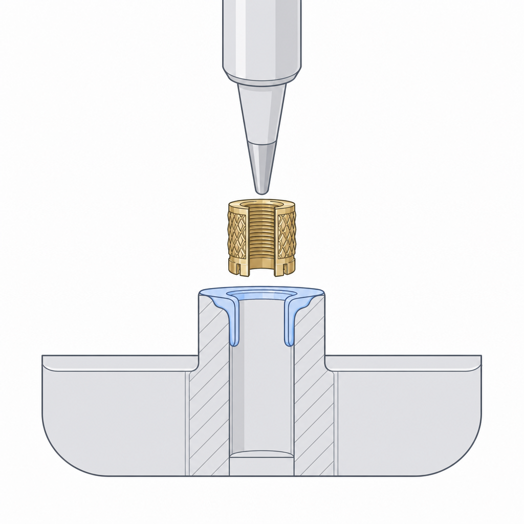
If you want a thread in a printed part that survives being assembled and taken apart fifty times, stop printing the thread and melt in a brass one. A heat-set insert is a knurled brass sleeve, internally threaded, that you push into a pilot hole with a hot soldering iron. The brass melts the surrounding plastic, the part flows into the knurls, and when it cools you have real metal threads anchored in your boss. For M2 through M5 — exactly the sizes where printed threads strip — this is the most reliable joint you can design.
Why they beat printed threads
A printed thread is plastic crests stacked from layers, weak across the grain and rough on the flanks. A heat-set insert puts the load-bearing thread in brass and spreads the pull-out force across a knurled cylinder gripping the plastic, not a few fragile ridges. You can run a steel machine screw straight into it at full torque. It's the difference between a panel screw you trust and one you replace.
The whole scheme lives in the boss — the cylinder of plastic you model to receive the insert. Get the boss right and the insert does the rest.
Sizing the boss and pilot hole
Two numbers matter: the wall of plastic around the insert, and the hole it melts into.
Boss outer diameter ≈ 2× the insert OD. The molten plastic has to go somewhere as the insert pushes in, and it needs enough wall around it to resist splitting. A boss roughly twice the insert's outer diameter gives a solid collar. Thinner than that and the boss cracks down a layer line as the brass goes hot.
Pilot hole slightly smaller than the insert OD. The hole should be a little under the insert's outer diameter so the knurls bite, but follow the manufacturer's recommended hole size — inserts vary by brand and the datasheet number is the one that grips without splitting the boss. Print a test boss and check before committing a panel of them.
| Thread | Insert OD (approx) | Pilot hole Ø |
|---|---|---|
| M3 | ~4.6 mm | ~4.0 mm |
| M4 | ~5.6 mm | ~5.3 mm |
| M5 | ~6.4 mm | ~6.4 mm |
Treat the table as a starting point. Exact insert OD and recommended hole differ between suppliers — the datasheet wins every time.
Chamfer the mouth and give it depth
Add a small lead-in chamfer at the top of the hole. It centres the insert as you set it, catches the first bit of displaced plastic instead of squeezing it up around the rim, and leaves a clean flush face. A 45° chamfer about the size of the wall thickness is plenty.
Make the hole as deep as the insert is long, plus a hair more so the insert can seat flush or just below the surface. A short hole leaves the insert standing proud, fouling whatever bolts down on top of it.
Where they shine
Reach for heat-set inserts anywhere a printed part bolts to something and will be opened again: enclosure lids screwed down over a PCB, a motor mount that gets re-shimmed, battery doors, anything you service. Model the bosses into the wall from the start — far easier than gluing nuts in afterward, and unlike a printed thread it won't strip the third time a customer opens the case.
For threads too big to bother with an insert — knobs, caps, anything M6 and up — printing the thread directly is fine; see Modelling threads. And when you want the fastener to come from the back of a part rather than threading into it, a captive nut is the move: see Captive nuts and bolt clearances.