Walls, perimeters and infill
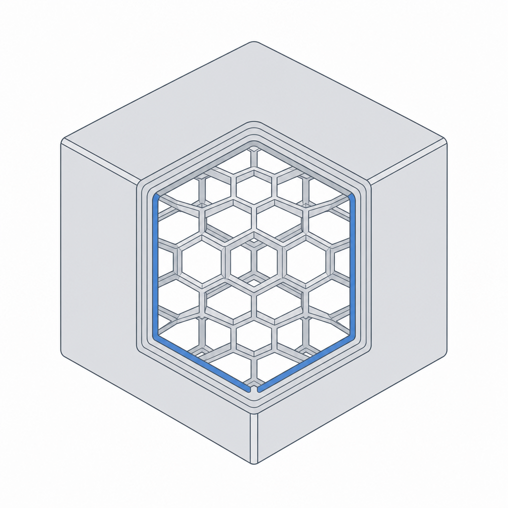
Here is a fact that surprises everyone new to printing: a "solid" printed part is mostly empty inside. The printer draws a few outer loops — the walls — and fills the space between them with a sparse internal lattice — the infill. A 20 mm cube set to 20% infill is about four-fifths air. Once you can picture that shell-and-lattice structure, designing parts that are strong, light and cheap to print stops being guesswork.
The anatomy of a printed wall
Look at any printed part edge-on and you'll see the outer surface is made of a small number of side-by-side loops. Each loop is one pass of the nozzle, called a perimeter. Two or three perimeters form the wall; the top and bottom are capped with a few solid layers; everything inside is infill.
The number that ties this together is the line width — how wide one extruded bead is, set by the nozzle. A 0.4 mm nozzle lays a line about 0.45 mm wide. So a "wall" is really N perimeters × line width: two perimeters make a wall about 0.9 mm thick, three make about 1.35 mm.
Design walls as whole multiples of line width
This is the single most useful wall rule, and almost nobody is told it: make your walls a whole number of line widths thick.
If you draw a 1.0 mm wall on a 0.45 mm line, the slicer can fit two perimeters (0.9 mm) and is left with a 0.1 mm sliver it cannot fill — so it either leaves a hollow gap down the middle of your wall (weak) or overlaps and bulges. Draw that wall at 0.9 mm (or 1.2, or wider) and every perimeter lands cleanly. The wall is stronger and the surface is nicer, just from picking the right number.
| Perimeters | Wall thickness | Use for |
|---|---|---|
| 1 | ~0.45 mm | nothing structural — too fragile |
| 2 | ~0.9 mm | light parts, enclosures, brackets |
| 3 | ~1.35 mm | most functional parts |
| 4 | ~1.8 mm | parts that take real load |
Infill: what it does and what it doesn't
Infill is the lattice between the walls. Its first job is humble but essential: it gives the top layers something to print onto so they don't sag into the hollow interior. Its second job is to add some stiffness and impact resistance.
What infill is not is a linear strength dial. Going from 20% to 40% roughly doubles the print time and plastic but adds far less than double the strength, because most of a part's strength lives in its walls, not its core. If a part flexes or breaks, your first move should be more perimeters, not more infill.
- 15–20% — the everyday default; fine for most parts.
- 25–40% — parts that take moderate load or impact.
- 50%+ or solid — rarely worth it; thicker walls usually win for less time.
Minimum features that actually survive
Because nothing can be thinner than one line, there is a floor on what you can print. Design below it and features come out fragile, fuzzy, or missing entirely.
| Feature | Minimum that works |
|---|---|
| Structural wall | ~0.8 mm (two perimeters) |
| Free-standing pin / post | ~2 mm diameter |
| Embossed (raised) detail | ~0.8 mm wide, ~0.6 mm tall |
| Engraved (recessed) detail | ~0.5 mm wide, ~0.4 mm deep |
| Text height | ~6 mm, embossed, prints more reliably than engraved |
Put these together and a strong, efficient part has a clear recipe: walls sized to whole perimeters and carrying the load, a modest infill just dense enough to hold the top up, and no feature smaller than the printer can draw. Thick where it matters, hollow where it doesn't.