A quick stress check with FEA
You've designed a bracket. Will it hold? You could print it, hang the load on it, and watch it snap — or you could ask the part before you commit any plastic. A built-in simulation is coming to Kapy: pin the part down, push on it, and see where the stress piles up and how far the part bends. Used honestly, it turns "I think this is strong enough" into "I can see exactly where this will fail first." Used naively, it lies to you with confident colours. This article is about telling those two apart — so you're ready the day it lands.
What the simulation will do
The tool runs a quick finite-element analysis (FEA). You give it three things — where the part is held, where the load is applied, and how hard — and it computes how the part deforms under that load. Out the other side you get two readouts worth your attention:
- Von Mises stress — a single number per point that summarises how close the material is to yielding. The hot spots are where things break.
- Displacement — how far each point moves. This is your stiffness check: a bracket that's "strong enough" but deflects 4 mm under load is still useless.
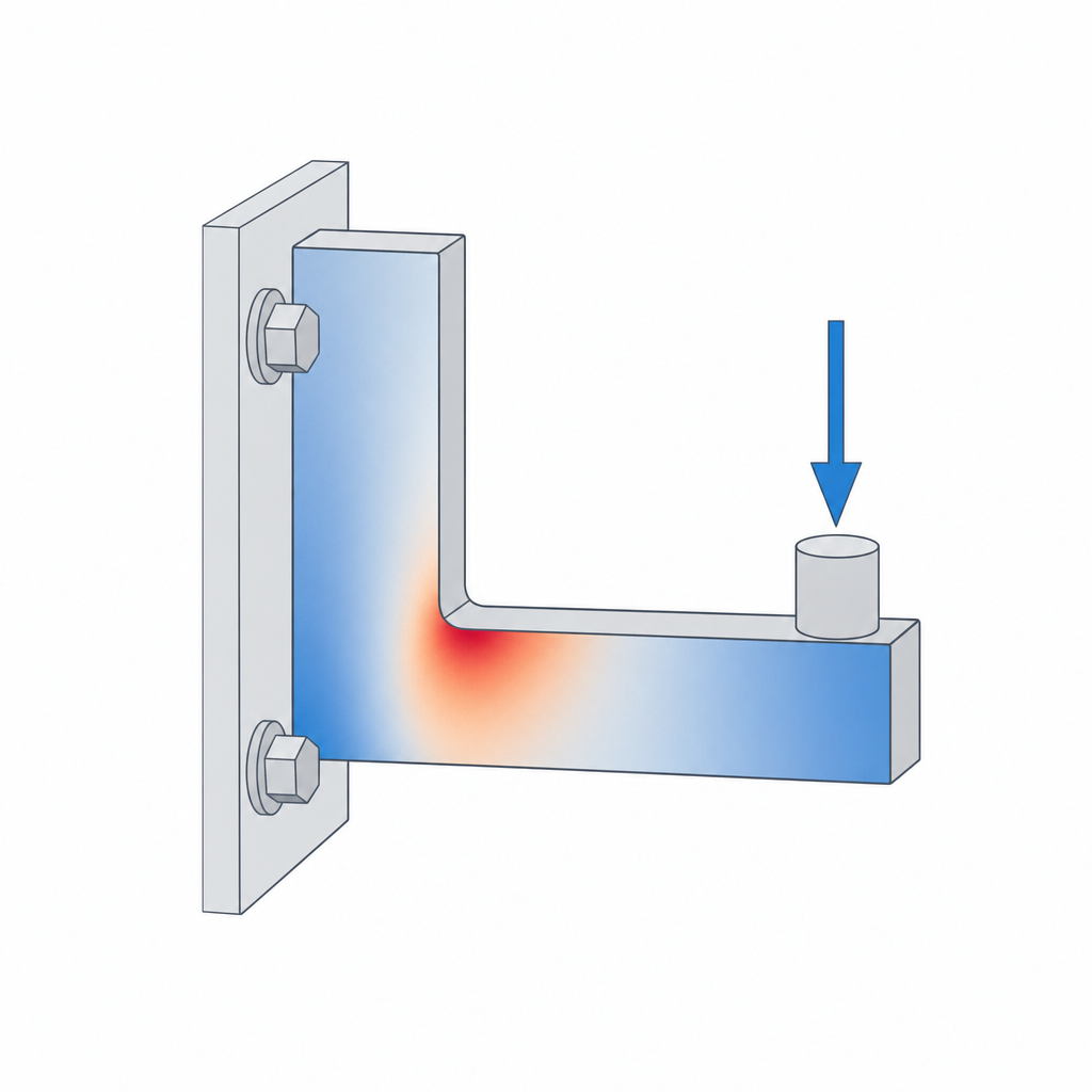
The colour map does the talking. A part that's mostly cool blue with one angry red speck has a stress concentration — usually a sharp inside corner — and that speck is where the crack will start.
The workflow: constrain, load, run
The sequence is always the same.
- Constrain. Fix the faces that are actually bolted, clamped, or resting against something. This is the step people get wrong: constrain a face that's free to move in reality and you'll invent stiffness the part doesn't have.
- Load. Apply the force where it really lands — the bearing seat, the hook, the screw boss — and in the direction it really pushes. Use a realistic number, in newtons.
- Run, then read. Look at the von Mises map first to find where, then the displacement map to judge how much.
Change one dimension, run it again, and compare. That comparison is where FEA earns its keep.
The caveat that makes or breaks this
Here's the part most tutorials skip. The solver assumes your part is solid and isotropic — one uniform block of material, equally strong in every direction. Your printed part is neither. It's mostly hollow (walls wrapped around sparse infill — see Walls, perimeters and infill) and it's anisotropic: far weaker between layers than along them, because the layer bonds are the weak link (see Layer adhesion and anisotropy).
So the stress numbers the solver hands you are not the stress your printed part will see, and the strength it implies is optimistic — often badly so in the layer direction.
How to use it honestly
Lean into what FEA is genuinely good at: telling you where the stress is and which of two designs is stiffer. Those answers survive the solid-isotropic assumption because they're comparative.
- Find the concentration, then fix it. A red speck at an inside corner is your cue to add a fillet, a rib, or a gusset — see Ribs, gussets and fillets. Re-run and watch the peak drop.
- Put material where the stress lives. The cool blue regions are carrying almost nothing. That's a direct invitation to trim them — the whole premise of Lightweighting.
- Orient for the load. If the worst stress runs across the layers, remember the part is weakest there and reorient the print accordingly.
The honest summary: FEA won't tell you whether your bracket holds 600 N. It will tell you that the inside corner is the problem, that version B is stiffer than version A, and where the metal — sorry, the plastic — is going to waste. That's plenty.