Why we wrote our own constraint solver
Drags that take over a second and dimensions that flip a segment: why KapyCAD 2 will have a sketch solver of its own.
Part 5 of the series Inside KapyCAD 2, about the solver that will debut in KapyCAD 2, which we're still building. In how we solve your sketches we explained the mechanism: you draw, you add rules ("these two lines are parallel", "this side is 40") and a constraint solver moves the points until every rule holds. That solver is PlaneGCS, FreeCAD's sketch solver, compiled for the browser: it's today's solver in KapyCAD, and it has served us very well from day one.
In KapyCAD 2 we'll replace it with our own, written in Rust, which will live inside the Rust core of the document. This part covers why, and what it will do differently.
What hurts
Switching solvers isn't something you do lightly. With today's solver (PlaneGCS) we have a list of measured problems in front of us, and chances are you've hit at least one of them:
- Slow drags on big sketches. On one of our calibration sketches, a drag frame takes 48 ms at the median, but the 95th percentile (p95) reaches 1.16 s and the worst frame 1.7 s. You drag a point and the sketch sits there thinking.
- Dimensions that flip a segment. You change a value and a corner jumps to the other side, like a triangle reflected in a mirror. On our "dimension ladder" (a test that walks dimensions up and down on real sketches) we counted 88 such cases.
- False conflicts: a tiny drag can leave the sketch "over-constrained" without you adding a single constraint.
- Tangencies with a residual error. In offsets, where a line flows smoothly into an arc, an error of about 0.06° is left after a drag. You can't see it, but it isn't zero.
- Unreliable diagnostics. Sometimes a dimension that is holding the sketch together shows up as "safe to delete".
All of these figures come from our own measurements during development, on real sketches from our test corpus.
Patch or rewrite
None of those problems is a PlaneGCS "bug" in the strict sense. PlaneGCS is a general numeric solver, designed around FreeCAD's workflow, and it does what it promises very well: find a solution that satisfies the equations. We also want things an arbitrary solution doesn't guarantee: that it stays on the same branch your sketch was on, that it moves as little as possible, and that the diagnosis is exact.
So we've kept adding workarounds bolted on from outside: restarts when something flips, extra passes during a drag, a redundancy check with timeouts, several solves in a row to decide whether a new constraint is superfluous… When we took stock, almost half of the roughly 12,000 lines around the solver were just that: workarounds.
A workaround bolted on from outside has a limit. If the solver doesn't know a tangency has a side, you can detect afterwards that it switched sides and undo it, but you can't stop it from trying. We decided to move those ideas into a solver of our own, and the workarounds will go when PlaneGCS does.
Ground rules for the new solver
Before writing a line of the new solver, we agreed on three rules.
Orientation is part of the data
Many constraints have two equally valid answers: a line tangent to a circle can touch it with the centre on one side or the other; two tangent circles can touch externally or one inside the other; two parallel lines can point the same way or opposite ways, and a perpendicular can turn one way or the other. Today the solver picks. In KapyCAD 2 each of those constraints will store its sense (a plain +1 or −1) and the equations will be signed, so the other branch will no longer be a solution.
The documents you already have don't carry that field. For them, the stored geometry will be the intent: the side the tangency is on is the side it keeps. The sense will be written the first time you edit that sketch, never when you open it, so a document nobody touched doesn't show up as modified. If you ever want the other branch, the constraint's menu will have a "Flip" button.
Opening moves nothing
If you open a document whose constraints already hold, the solver will move nothing; it's the rule we described in Part 2, applied to sketches.
Move the minimum
When you change a dimension, there are infinitely many ways to satisfy it. The solver will pick the one that moves everything else the least.
Inside the solver, without the maths
A constraint solver, stripped of its geometry, takes only a few lines to describe.
First come the variables: the coordinates of each point, the radius of each circle, the angle of each gear. Then the residuals: for each constraint, a number that is zero when it holds. A 40 mm dimension between two points has the residual "current distance minus 40". Solving the sketch means finding values for the variables that bring every residual to zero.
In the development build, the solver uses Gauss–Newton for that, a classic method: you look at how wrong each residual is and which way it would change if you nudged each variable, you take a step that corrects that error, and you repeat until everything adds up. Each step carries a little "damping" (Levenberg's trick) so it doesn't overshoot when the problem gets hard.
The whole thing rests on the minimum norm. A sketch with freedom has many ways to satisfy its constraints. Of all the possible steps, the solver takes the shortest: the one that touches as little as possible. That's why opening moves nothing (if it already holds, the shortest step is to stay put) and why whatever you didn't touch stays where it was.
Not every equation weighs the same, either. Your constraints are hard: they hold, full stop. Below them sit the soft ones, wishes like "the point you're dragging, as close to the cursor as possible", which hold as far as the hard ones allow and never at their expense. Last come the weak ones, gentle preferences like "everything else, where it was". The solver satisfies the hard constraints first, then the soft ones within the freedom the hard ones leave, then the weak ones within what's left.
There's one more guarantee: the solver refuses any step that would flip a segment (pushing it through zero length) or move a tangency to the other side. If it doesn't converge, it returns the best valid state it visited and reports that it didn't converge.
Trivial constraints that aren't solved
Many constraints in a real sketch are so simple that treating them as equations is a waste: "these two points coincide", "this line is horizontal", "this point is fixed", "this point sits on the axis".
The new solver gets them out of the way before it starts by folding them. Two coincident points become a single point. A horizontal line makes its two ends share the same vertical coordinate, which becomes one variable. A fixed point leaves the system and turns into a constant.
The system that's left is smaller and solves sooner, and the diagnosis of these constraints becomes exact, with no numerics. If you close a loop of horizontals where one already follows from the others, it's caught while folding, and so is fixing the same point in two places; the warning will name the chain of constraints it clashes with.
The same goes for pattern copies: each copy is the exact transform of its original and has no variables of its own. A constraint on the copy acts on the original.
Gears that roll
Sketch gears were one of the places where having the solver in-house shows the most.
Today a gear's radius is a continuous number and the tooth count comes from
rounding it, so the teeth can end up slightly mis-spaced. In KapyCAD 2 the
tooth count will be an integer that's stored, and the pitch radius will
derive from it: r = m·z/2, with m the module and z the teeth. Dragging
won't change z; to change it you'll edit it in a small label at the gear's
centre. If one of your dimensions says something else about the radius, your
dimension will win.
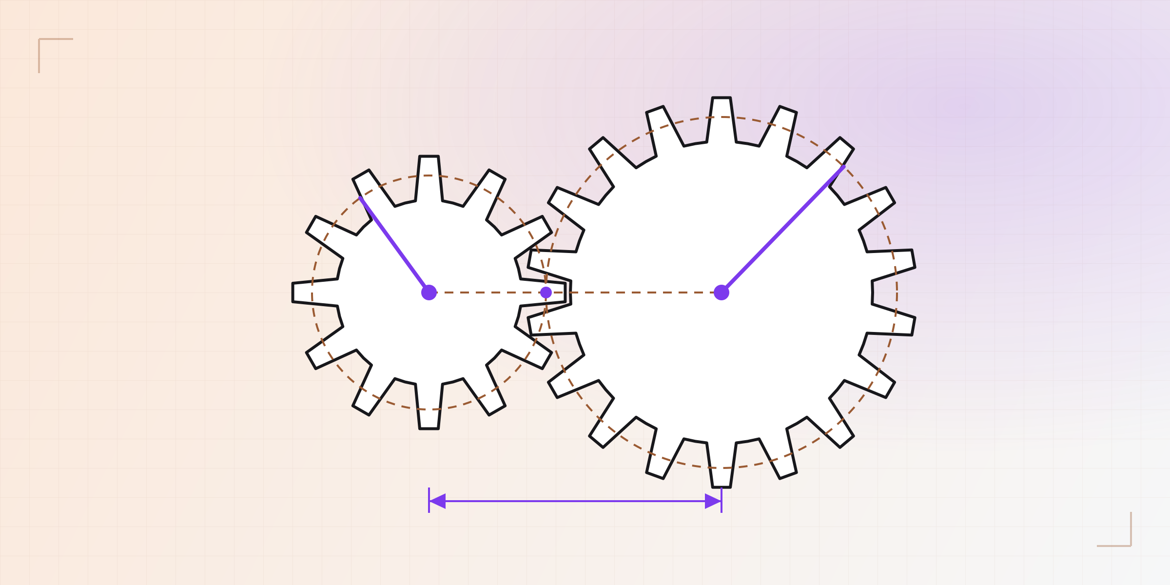
When two gears mesh, the solver will also know they roll together. Each gear's angle is one more variable, and the mesh imposes a rolling relation: turn one, and the other turns the opposite way with the ratio of their teeth. Drag one gear's pitch circle and the whole chain will turn with it.
There's one more detail: with the rolling relation alone, the teeth could interlock or collide depending on how they started. So when the mesh is created, a phase will be computed and stored: the starting angle that drops each tooth into a gap of the other. That phase keeps every tooth in its gap, however much the gears turn.
Full gear trains (choosing how many teeth each wheel gets to approach a target ratio) will still have their own routine. That's an integer problem and we don't ask the solver to do it.
How we validated it before switching
We couldn't validate the new solver by demanding the same answers as PlaneGCS, because we wanted different answers in the cases that failed. We measured it with the four judges from Part 1, which we wrote before the solver. The ones for opening without moving anything, zero flips and exact diagnosis are green. The speed judge measures two things: while dragging, it's green too; when a change is confirmed, it's still red for a handful of sketches that solve slightly slower than before and are on our list.
Results
In our measurements during development, opening a sketch moves nothing across the whole corpus, and the dimension ladder no longer flips a single segment. In KapyCAD 2 tangent joints in offsets will be exact, without the 0.06° left today. The diagnosis will change too, with the degrees of freedom counted right and conflicts narrowed down to the constraints that clash; we cover this in Part 7.
On speed, a full warm solve costs us about 5 ms in the browser against 6.5 ms with today's solver, and the corpus total drops from 696 to about 335 ms, although the handful of sketches still red on confirming a change are over their baseline. The PlaneGCS module (429 KB uncompressed) will be gone; the linear-algebra library we use adds about 100 KB, about 45 KB compressed.
In the first tests, a 5.3 mm dimension came out as 5.29999999925, the same number Part 1 opened with. It was within tolerance and, for practical purposes, the same, but the 3D geometry built from that sketch gave the same part different names. So in the new solver, an answer that converges is polished down to the last bit.
Part 6 moves on to dragging: what will happen when you pull on a point, and how the new solver will keep the sketch from jumping while you do.
Written by
Sergio
Building Kapy CAD — parametric 3D modelling for 3D printing, in the browser.


