kapycode: your model as text
In KapyCAD 2 every document will have a readable text form, kapycode, and you'll be able to go from the text to the editor and back without losing anything.
Part 8, the last in the series Inside KapyCAD 2; what it describes will arrive with KapyCAD 2, which we haven't released yet. A parametric model is, at heart, a recipe: draw this sketch, extrude it ten millimetres, round these edges. In KapyCAD that recipe is already there, in the operation history. What it lacks is a form you could read straight through, copy, compare or write yourself.
In KapyCAD 2, every document will have a text form, and we call it kapycode. It's the same document, written another way.
A model you can read
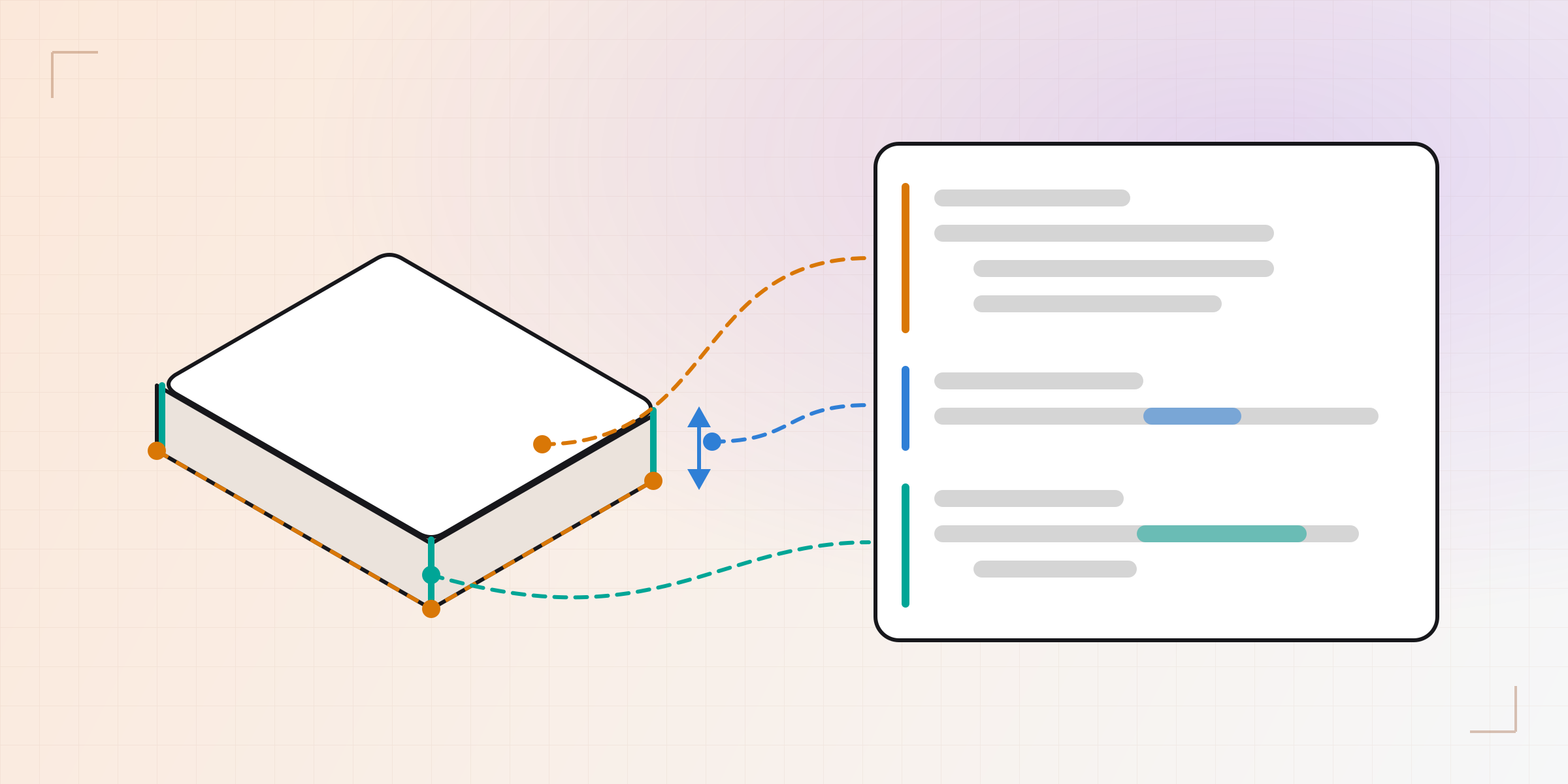
Let's start with an example. This is a 50 × 30 millimetre box, extruded 10 and
with its four vertical edges rounded. This is how the development build
writes it; we've left out a few fields (where you see …) so it fits:
@name("Sketch 1")
sketch sketch_1 on FacePlane(…):
    origin = (=0, =0)
    p_4f288929 = (50, 30)
    p_71df89f1 = (0, 30)
    p_92663e95 = (50, 0)
    L_09bfea4f = line(origin, p_92663e95)
    L_499b27c9 = line(p_4f288929, p_71df89f1)
    L_8271bf8e = line(p_92663e95, p_4f288929)
    L_a7ba82a2 = line(p_71df89f1, origin)
    horizontal L_09bfea4f
    horizontal L_499b27c9
    vertical L_8271bf8e
    vertical L_a7ba82a2
    dist origin p_92663e95 = 50
    dist origin p_71df89f1 = 30

@name("Extrude 1")
extrude_1 = extrude(combineMode="new", endCondition="blind", height1=10, sketchId=sketch_1, …)

@name("Fillet 1")
fillet_1 = fillet(edgeQuery=edges() where vertical, radius=2, targetBodyId=body_1, …)
It almost reads itself. A sketch with four points and four lines (the odd names
are each element's internal identifier). One corner is the origin, which the =0
pins in place; two sides are horizontal and two vertical, and two dimensions set
the width to 50 and the height to 30, so the rectangle is fully constrained. Then
an extrusion of 10 that uses that sketch, and a fillet of radius 2 on the
vertical edges of the body.
The @name lines are the names you see in the history.
There's only one way to write each thing. The text comes from a canonical formatter, like the ones many programming languages ship with: four-space indents, one statement per line, no style options. Two identical documents give the same text, byte for byte. The round trip and the diffs below both depend on that.
There and back without loss
Generating the text from the model is the easy part. What matters is coming back: edit the text, go back to the editor, and the document is what the text says. And if you don't touch anything, the document that comes back is identical to the one that left.
"Identical" is a strong word, so we measure it on every change with two kinds of tests. The first uses a synthetic document built to go through everything the format can say: all thirty operation kinds, every variant of every field, every possible value of every closed list, every optional field both present and absent. The second goes through more than fifty real documents, the set we use for this check: the models from the tutorials, parametric generators and geometry test parts. Each one is turned into text, read back and compared with the original field by field.
Both count four things: values that change on the trip, lists that come back in a different order, pieces the text can't express and has to keep as an opaque block, and parts of the format no document reaches. All four are at zero, and the rule is they can't go up. On top of that, the geometry reference documents are opened from their text and regenerated: volumes, areas, boxes, faces and edges have to come out the same as when they're opened the normal way.
The only thing the text leaves out is what can be recomputed: a sketch's status or its degrees of freedom, for example. They come from running the recipe, so there's no need to write them down.
If the text you write has an error, nothing will be applied. The part will stay in its last good state, and the error will be marked on its line.
What it's for
Having your model as text is useful in several ways. Some will come with KapyCAD 2; others will come later.
The first is Smart Objects written in code. When we introduced Smart Objects we mentioned that some of them are defined by code. In KapyCAD 2 that code will be kapycode, the same language. For example, a peg with two parameters:
smartobject peg:
    param d: Length = 10
    param tall: Length = 16
    sketch s on XY:
        c = (0, 0)
        circle(c, d / 2)
    return extrude(s, tall)
An interpreter inside the KapyCAD core will run it, and it will be deterministic: with no clock and no randomness, the same code with the same parameters will build the same thing on any machine. And it will have a work budget: a loop that never ends will be cut off with a clear error instead of hanging the tab.
You'll also be able to review changes as a diff. Because the text is canonical and names don't renumber themselves (more on that below), a small change to the model is a small change to the text. If you raise the extrusion from 10 to 24:
-extrude_1 = extrude(combineMode="new", endCondition="blind", height1=10, sketchId=sketch_1, …)
+extrude_1 = extrude(combineMode="new", endCondition="blind", height1=24, sketchId=sketch_1, …)
The diff is one line. The file you download from KapyCAD 2 will be that same text, with the format version on its first line, so any tool that compares text will show you what changed between two copies of your model.
And you'll be able to start from something that already exists. A fragment of text can be copied and pasted, so a part you always begin the same way becomes a snippet you paste in.
The code panel
In KapyCAD 2, Design mode will have a code panel next to the viewport, with
your model in kapycode. Text and editor will stay in sync both ways: change
height1=10 to height1=24 and the part grows; move something in the editor and
the text updates. What you type only applies once it parses and resolves without
errors, so a half-written line never leaves the part half-built. And there's a
single undo stack for both: Ctrl+Z undoes your changes in order, whether you
made them in the text or in the editor.
The panel's questions are answered by the language helper from Part 4, so typing never waits for a regeneration to finish.
Names that don't break
In text, it's obvious how one line refers to another.
sketchId=sketch_1 says which sketch the extrusion uses. What happens if you
delete an earlier operation?
In a naive version, names would come from the order: extrude_1, extrude_2…
Delete the first one, the second becomes extrude_1, and every line that cites
it changes even though you didn't touch it. In KapyCAD 2 each operation's name
will be stored: it's born when you create it and only changes if you rename it.
And if you rename it from the panel, all its references will change with it.
A name that doesn't exist won't slip through either. If you write
sketchId=sketch_7 and there's no sketch_7, that line will be marked as an
error and the document will stay as it was.
Faces and edges are the hard case, and here the text inherits all the work we
described in stable topological
references.
Instead of saying "edge number 4", a reference to an edge describes how it was
born: which operation created it and from what. In the text it shows up that
way, for example with bornIn=extrude_1 and the role it had.
For many cases there's something better still: a rule. The
edgeQuery=edges() where vertical in the example describes how to find the
edges without listing them. Turn the rectangle into a notched profile and the
rule searches again and finds whatever vertical edges there are now. Rules
accept filters like vertical, horizontal or circular, measurements like
length > 10, and set combinations.
And when a text edit really would break references (say, rewriting a sketch's rectangle as a circle while a fillet hangs off its edges), KapyCAD 2 won't apply it blindly: it will tell you how many elements and how many references would be lost, and let you choose between "Apply anyway" and "Go back".
What's next
This part describes where we're heading, with no commitments and no dates. A model that is text, with a language that reads well and runs deterministically, is a very good foundation for two things.
The first is automation: generating variants of a part or applying the same change to many. We hold ourselves to one rule for that: anything that can be written has to correspond to something you can already do from the interface, so the text will never be able to do anything the interface can't.
The second is an AI that writes kapycode. A compact text format, with precise errors on their line and a checked round trip, is the kind of thing an assistant can work well with, and one where you can review its changes before accepting them.
Wrapping up the series
This part closes Inside KapyCAD 2. If you're just arriving, here's the full series:
- How do you test CAD software?: how we catch the bug you can't see, the face that quietly moves 0.2 mm.
- Update without fear: your files open exactly as you left them: a format that changes and parts that still open the same.
- Our own OpenCascade: the geometry kernel, built and maintained by us.
- A Rust core for the whole document: where the entire model will live in KapyCAD 2.
- Why we wrote our own constraint solver: to stop patching and write a purpose-built sketch solver.
- Dragging without the sketch jumping: how the sketch will follow the cursor and not jump when you let go.
- Which of your constraints is redundant?: a diagnosis that names only the constraints that are redundant or clash.
Part 8 is this one: kapycode, your model as text.
Written by
Sergio
Building Kapy CAD — parametric 3D modelling for 3D printing, in the browser.


