Learn: two in-depth guides to designing parts that actually work when printed
Kapy CAD's Learn hub is live: 139 articles —in English and Spanish— on tolerances, strength, threads and printed mechanisms, with diagrams, schematics and 3D animations of real catalog parts.
Designing a pretty part on screen is easy. Getting it off the printer so it fits, turns and holds is another story: molten plastic doesn't behave like machined metal, and almost everything you know from "classic" CAD bends a little on its way through a 0.4 mm nozzle. So we wrote Learn: the manual we wish we'd had when we started designing for FDM.
Today we're opening two complete guides, each built from the physics up to concrete dimensions you can drop into your model today.
What's inside
- Printing parts that fit — 23 articles across 6 blocks: how FDM shapes your design, orientation and overhangs, walls and infill, tolerances and fits, strength and structure, threads and fasteners, model to print, and validation.
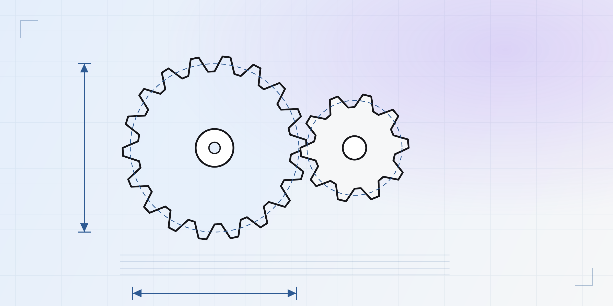
- Building mechanisms — 116 articles across 17 sections: from the fundamentals (tolerances, anisotropy, embedded hardware) all the way through sixteen families of mechanisms: permanent and removable joints, articulations, linear guides, gears, belts and chains, cams and cranks, couplings, intermittent motion, bistables, anti-return, springs, linkages, buttons and controls, structures and metamaterials, and gadgets.
That's 139 articles in total, every one in English and Spanish. These aren't four-line entries: each one reasons about the why in physical terms, gives real numbers, names the failure modes, and ends by linking to what comes next.
Not generic theory — it's FDM
The difference is in the details that only matter once you print. A couple of examples of what you'll find:
- Why zero clearance on screen is interference in the part. The hole comes out small and the shaft large —in opposite directions— because half the bead bites inward on a concave wall and bulges out on a convex one. That's why clearance is reasoned per side, and why a mechanism is designed by opening the gap on purpose.
- Why a press-fit boss splits along the seam, not through the plastic. Hoop stress doesn't break sound material: it unzips the vertical line where the perimeter starts and ends. Sometimes moving that seam in the slicer fixes the crack for free.
- The four ways to make a screw hold in a printed part —printed thread, self-tapping, captive nut, heat-set insert— and when to use each, depending on how many times you'll take it apart.
With diagrams, schematics and mechanisms that move
Learn isn't just text. It ships 17 interactive decision-and-family diagrams, 86 schematic illustrations (cross-sections, force diagrams, before/after), and more than 30 3D animations — and here's the nice part: every animation drives the real parametric model from the catalog, with its actual kinematics. No pre-recorded videos, no drawings: it's the part, moving.
Watch a planetary reducer actually mesh —sun, planets and ring, with the teeth rolling instead of clipping through each other:
Or the Trammel of Archimedes, two perpendicular sliders that make the end of the arm draw a perfect ellipse:
And there are many more: a four-bar articulating, the Klann walking leg, a scissor extending, a box that folds itself up, a flexible chainmail sheet. Every mechanism you see move in its article is a part you can fork and drop into your own design.
And this is only the beginning
Learn will grow with the catalog: every new mechanism brings its article, its animation and its ready-to-use part. Head over to the learn section, look up whatever you're about to print, and tell us what's missing — we'll write it.
Written by
Sergio
Building Kapy CAD — parametric 3D modelling for 3D printing, in the browser.
